Facebook
 Google
 GitHub
 Linkedin
Si Lab - Full-wave Bridge Rectifier
Project Overview
The circuit of Figure 1 uses four diodes to provide full-wave rectification without the necessity of a center-tapped transformer.
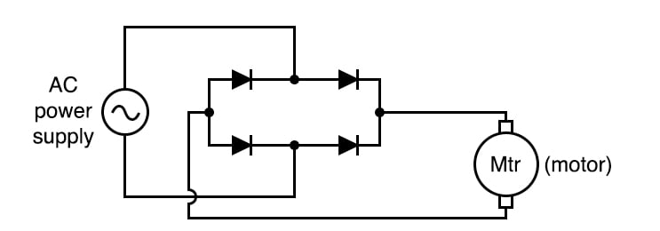
Figure 1. Schematic diagram of the full-wave bridge rectifier circuit driving a motor
Can you trace the current path from the AC power supply through one diode, through the motor, through a second diode, and back to the AC power supply for both the positive and negative half-cycles of the AC supply voltage?
In applications where a center-tapped or split-phase source is unavailable, this is the only practical method of full-wave rectification. The advantages of the circuit include its simple design and low-cost components.
However, in addition to requiring more diodes than the center-tap circuit, the full-wave bridge suffers a slight performance disadvantage as well. The additional voltage drop is caused by the current having to go through two diodes in each half-cycle rather than through only one.
Parts and Materials
- Low-voltage AC power supply (6 V output)
- Four 1N4001 rectifying diodes
- Small hobby motor, permanent-magnet type
Learning Objectives
- Design of a bridge rectifier circuit
- Advantages and disadvantages of the bridge rectifier circuit, compared to the center-tap circuit
Instructions
Step 1: Build the full-wave bridge rectifier circuit using the four silicon diodes, as illustrated in Figures 1 and 2.
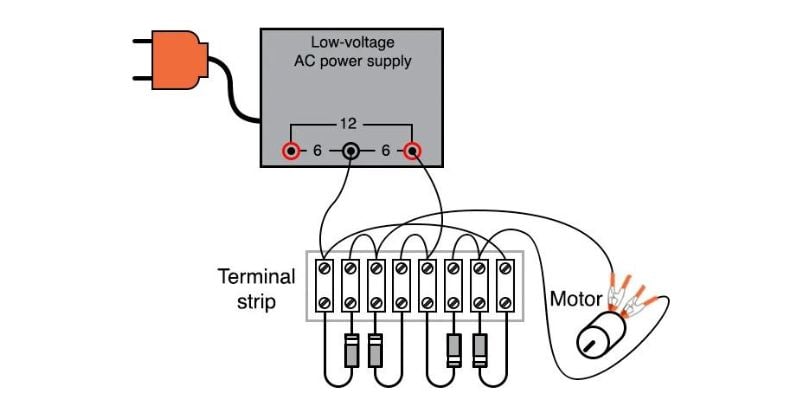
Figure 2. Terminal strip implementation of the full-wave bridge rectifier circuit driving a motor.
Step 2: Measure the DC voltage across the motor. Compare the DC voltage reading across the motor terminals with the reading obtained from the half-wave rectifier experiment, given the same AC power supply and the same motor. With a low-voltage source such as the one you’re using (6 V RMS or root mean square), the disadvantage of the two voltage drops for this full-wave bridge rectifier is easily measured.
SPICE Simulation of the Full-wave Bridge Rectifier Circuit
We can simulate the full-wave bridge rectifier using the circuit with node numbers, as illustrated in Figure 3.

Figure 3. SPICE circuit schematic for a full-wave bridge rectifier circuit
Netlist (make a text file containing the following text, verbatim):
Fullwave bridge rectifier
v1 1 0 sin(0 8.485 60 0 0)
rload 2 3 10k
d1 3 1 mod1
d2 1 2 mod1
d3 3 0 mod1
d4 0 2 mod1
.model mod1 d
.tran .5m 25m
.plot tran v(1,0) v(2,3)
.end
This simulation plots the input voltage as a sine wave that oscillates both positively and negatively. The output voltage is a series of positive humps corresponding to both the positive and negative half-cycles of the AC source voltage. The AC source is set to an 8.485 V peak corresponding to a 6 V RMS sine-wave voltage.
Related Content
Learn more about the fundamentals behind this project in the resources below.
Calculators:
Textbook:
Worksheets:
- Full-wave Bridge Rectifier Worksheet
- Rectifier Circuits Worksheet
- Peak, Average, and RMS Measurement Worksheet