Facebook
 Google
 GitHub
 Linkedin
Si Lab - Half-wave Rectifier
Project Overview
In this project, you will build and test the half-wave rectifying circuit, illustrated in Figure 1.
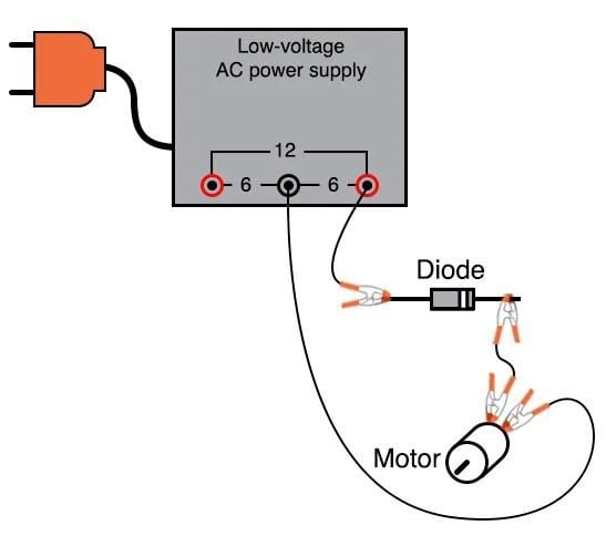
Figure 1. Half-wave rectifier circuit for motor drive.
Half-wave rectifiers are basic circuits for converting AC (alternative currents) voltages to pseudo-DC (direct current). They rely on the primarily one-way conduction of semiconductor diodes.
Parts and Materials
- Low-voltage AC power supply (6 VAC output)
- 6 V battery
- 1N4001 rectifying diode or any of the 1N400X series of rectifying diodes
- Small hobby motor, permanent-magnet type
- Optional: audio detector with headphones, built in the AC Lab projects
- Optional: 0.1 µF capacitor
A 0.1 µF capacitor is specified for coupling the audio detector to the circuit so that only AC reaches the detector circuit. This capacitor’s value is not critical. I’ve used capacitors ranging from 0.27 µF to 0.015 µF with success. Lower capacitor values attenuate low-frequency signals to a greater degree, resulting in less sound intensity from the headphones, so use a greater capacitor value if you experience difficulty hearing the tones.
Learning Objectives
- The function of a diode as a rectifier
- Permanent magnet motor operation on AC versus DC power
- Measuring ripple voltage with a voltmeter
Instructions
Step 1: Connect the motor to the low-voltage AC power supply through the rectifying diode, as seen in the illustration of Figure 1 and the schematic diagram of Figure 2.
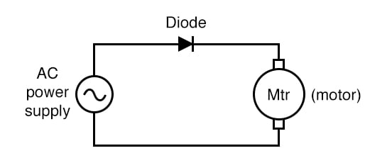
Figure 2. A half-wave rectifier circuit schematic.
The diode only allows current to pass through during the positive half-cycle of a full positive-and-negative cycle of power supply voltage, eliminating the negative half-cycle from ever reaching the motor. As a result, the motor only sees current in one direction, albeit a pulsating current, allowing it to spin in one direction.
Step 2: Take a jumper wire and short past the diode momentarily, as illustrated in Figure 3, noting the effect on the motor’s operation.
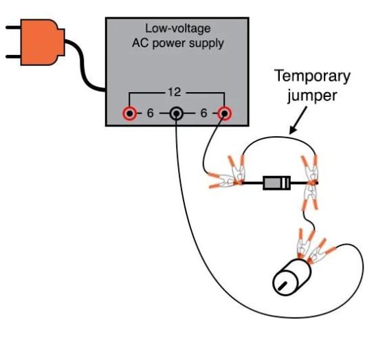
Figure 3. Bypassing the diode rectifier to drive the motor with AC.
As you should see, permanent-magnet DC motors do not function well on alternating current (AC).
Step 3: Remove the temporary jumper wire and reverse the diode’s orientation in the circuit. Note the effect on the motor.
Step 4: Return the diode to its original orientation, as shown in Figures 1 and 2. Measure the DC voltage and then the AC voltage across the motor, as illustrated in Figure 4.
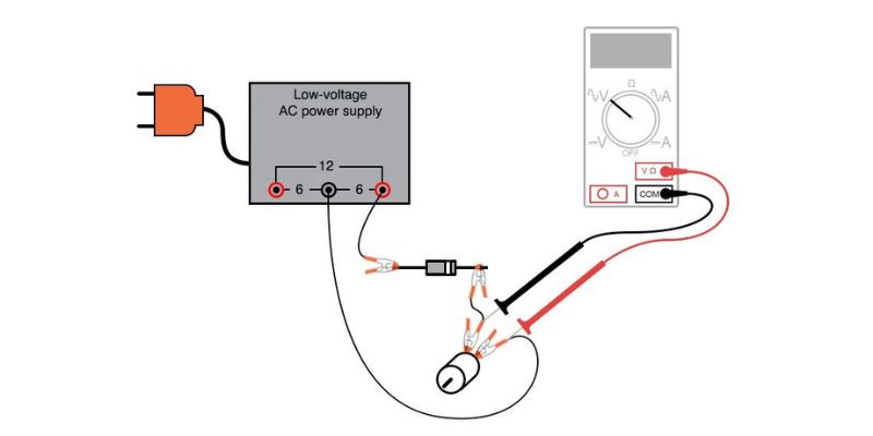
Figure 4. Measuring the voltage at the motor (shown with the multimeter set to measure AC voltage).
Most digital multimeters do a good job of discriminating AC from DC voltage. These two measurements show the DC average and AC ripple voltages, respectively, of the power seen by the motor.
Ripple voltage is the varying portion of the voltage, interpreted as an AC quantity by measurement equipment, although the voltage waveform never actually reverses polarity. Ripple may be envisioned as an AC signal superimposed on a steady DC bias or offset signal.
Step 5: Compare these measurements of DC and AC with voltage measurements taken across the motor while powered by a battery, as shown in Figure 5.
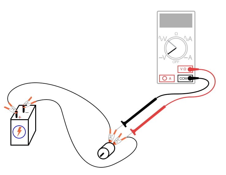
Figure 5. Measuring the voltage at the motor when powered by a battery.
Batteries provide pure DC power, and as a result, there should be little AC voltage measured across the motor in this circuit.
Whatever AC voltage is measured across the motor is due to the motor’s pulsating current draw as the brushes make and break contact with the rotating commutator bars. This pulsating current causes pulsating voltages to be dropped across any stray resistances in the circuit, resulting in pulsating voltage dips at the motor terminals.
Step 6 (Optional): A qualitative assessment of ripple voltage may be obtained by using the sensitive audio detector described in the AC Lab experiments chapter. This is the same device described as a sensitive voltage detector in the DC Lab experiments chapter. Turn the detector’s sensitivity down for low volume, and connect it across the motor terminals through a small (0.1 µF) capacitor, as shown in Figure 6.
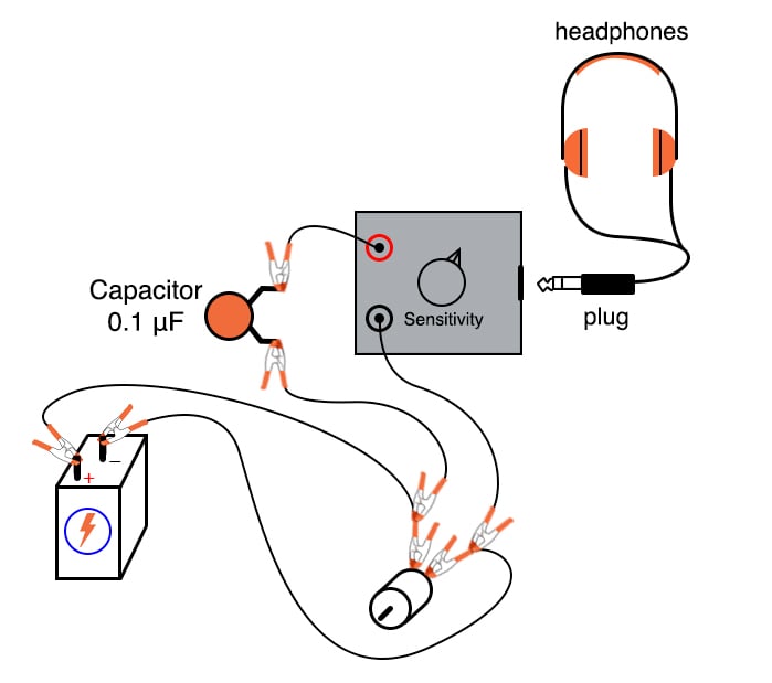
Figure 6. Connecting the sensitive audio detector to the battery-powered motor driver circuit.
With a battery powering the motor, the ripple should sound like a high-pitched buzz or whine.
The capacitor acts as a high-pass filter, blocking DC voltage from reaching the detector and allowing easier listening to the remaining AC voltage. This is the exact same technique used in oscilloscope circuitry for AC coupling, where DC signals are blocked from viewing by a series-connected capacitor.
Step 7 (Optional): Try replacing the battery with the AC power supply and rectifying the diode, listening with the detector to the low-pitched buzz of the half-wave rectified power (Figure 7):
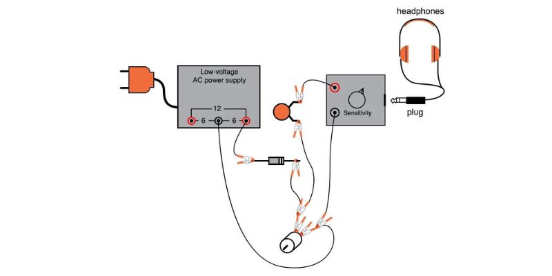
Figure 7. Connecting the sensitive audio detector to the half-wave rectifier motor driver circuit.
SPICE Simulation of the Half-wave Rectifier Circuit
We can simulate the half-wave rectifier circuit by adding SPICE node numbers, as illustrated in Figure 8.
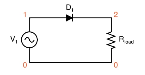
Figure 8. SPICE circuit schematic for a half-wave rectifier circuit.
Netlist (make a text file containing the following text, verbatim):
Halfwave rectifier
v1 1 0 sin(0 8.485 60 0 0)
rload 2 0 10k
d1 1 2 mod1
.model mod1 d
.tran .5m 25m
.plot tran v(1,0) v(2,0)
.end
This simulation plots the input voltage as a sine wave and the output voltage as a series of humps corresponding to the positive half-cycles of the AC source voltage. The dynamics of a DC motor are far too complex to be simulated using SPICE, unfortunately.
The AC source voltage is specified as 8.485 V instead of 6 V because SPICE understands AC voltage in terms of peak value only. A 6 V root mean square (RMS) sine-wave voltage is actually an 8.485 V peak. In simulations where the distinction between RMS and the peak value isn’t relevant, I will not bother with an RMS-to-peak conversion like this. To be truthful, the distinction is not terribly important in this simulation, but I discuss it here for your edification.
Related Content
Learn more about the fundamentals behind this project in the resources below.
Calculators:
Textbook:
Worksheets:
- Miscellaneous Diode Applications Worksheet
- Precise Diode Circuits Worksheet
- Rectifier Circuits Worksheet
- Peak, Average, and RMS Measurement Worksheet