
 Facebook
 Google
 GitHub
 Linkedin
Discrete Semiconductor Devices and Circuits
Bipolar Transistor Biasing Circuits
21 questions By Tony R. Kuphaldt
-
Question 7 of 21
Explain how the following bias networks function:

Each one has the same basic purpose, but works in a different way to accomplish it. Describe the purpose of any biasing network in an AC signal amplifier, and comment on the different means of accomplishing this purpose employed by each of the three circuits.
Hint: imagine if the AC signal source in each circuit were turned off (replaced with a short). Explain how each biasing network maintains the transistor in a partially “on” state at all times even with no AC signal input.
Reveal answerThe purpose of any biasing network in an AC signal amplifier is to provide just enough quiescent current through the base to keep the transistor between the extremes of cutoff and saturation throughout the input signal’s waveform cycle.
Notes:All three biasing techniques are commonly used in transistor amplifier circuitry, so it behooves each student to understand them well. In each case, resistors provide a “trickle” of current through the base of the transistor to keep it turned partially “on” at all times.
One exercise you might have your students do is come up to the board in front of the room and draw an example of this circuit, then everyone may refer to the drawn image when discussing the circuit’s characteristics.
-
Question 8 of 21
Describe what the output voltage of this transistor circuit will do (measured with reference to ground), if the potentiometer wiper begins at the full-down position (common with ground), and is slowly moved in the upward direction (closer to V):

Reveal answerVout will decrease, from 10 volts to nearly zero volts, as the potentiometer wiper is moved closer to V.
Follow-up question: based on this result, would you be inclined to call this amplifier an inverting or a noninverting circuit?
Notes:Although this circuit is very simple, it is also very important to master. Be sure to discuss its operation thoroughly with your students, so they understand.
-
Question 9 of 21
If we were to apply a sinusoidal AC signal to the input of this transistor amplifier circuit, the output would definitely not be sinusoidal:
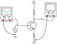
It should be apparent that only portions of the input are being amplified in this circuit. The rest of the waveform seems to be “missing” in the output, being replaced by a flat line. Explain why this transistor circuit is not able to amplify the entire waveform.
Reveal answerTransistors are essentially DC devices, not AC devices. Consider the base-emitter PN junction that the input signal is sent to: it can only conduct in one direction (base positive and emitter negative).
Notes:Sometimes it is helpful for students to re-draw the circuit using a transistor model showing the base-emitter junction as a diode. If you think this model would help some of your students understand the concept here, have another student draw the transistor model on the whiteboard, and use that drawing as a discussion aid. Like any PN junction, the base-emitter junction of a BJT only “wants” to conduct current in one direction.


