Facebook
 Google
 GitHub
 Linkedin
Discrete Semiconductor Devices and Circuits
Bipolar Transistor Biasing Circuits
21 questions By Tony R. Kuphaldt
-
Question 13 of 21
Explain how it is possible for a fault in the biasing circuitry of a transistor amplifier to completely kill the (AC) output of that amplifier. How and why can a shift in DC bias voltage have an effect on the AC signal being amplified?
Reveal answerIf the DC bias voltage shifts far enough away from the normal (quiescent) levels, the transistor may be forced into saturation or cutoff so it cannot reproduce the AC signal.
Notes:This question asks students to explore the possibility of complete AC signal failure due to a simple shift in DC bias, based on their understanding of how transistor amplifiers function. It may seem paradoxical that such a “small” fault could have such a large effect on an amplifier circuit, but it should make sense once students grasp how important bias is to class-A amplifier operation.
-
Question 14 of 21
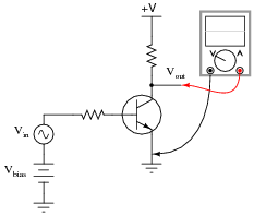
A student builds the following circuit and connects an oscilloscope to its output:
The waveform shown on the oscilloscope display looks like this:
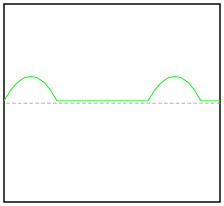
Definitely not Class-A operation! Suspecting a problem with the input waveform, the student disconnects the oscilloscope probe from the amplifier output and moves it over to the amplifier input terminal. There, the following waveform is seen:
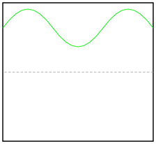
How can this amplifier circuit be producing such a distorted output waveform with such a clean input waveform? Explain your answer.
Reveal answerThe DC bias voltage (Vbias) is excessive.
Notes:Ask your students how they can tell the difference between excessive biasing and insufficient biasing, by inspection of the output waveform. There is a difference to be seen, but it requires a good understanding of how the circuit works! Students may be tempted to simply memorize waveforms (“when I see this kind of waveform, I know the problem is excessive biasing . . .”), so prepare to challenge their understanding with questions such as:
- What polarity of input signal drives the transistor toward cutoff?
- What polarity of input signal drives the transistor toward saturation?
- Where on the output waveform is the transistor in cutoff (if at all)?
- Where on the output waveform is the transistor in saturation (if at all)?
- Where on the output waveform is the transistor in its active mode?
Another point worth mentioning: some students may be confused by the phasing of the input and output waveforms, comparing the two different oscilloscope displays. For a common-emitter (inverting) amplifier such as this, they expect to see the output voltage peak positive whenever the input voltage peaks negative, and visa-versa, but here the two oscilloscope displays show positive peaks occurring right next to the left-hand side of the screen. Why is this? Because the oscilloscope does not represent phase unless it is in dual-trace mode! When you disconnect the input probe and move it to another point in the circuit, any time reference is lost, the oscilloscope’s triggering function placing the first waveform peak right where you tell it to, usually near the left-hand side of the display.
-
Question 15 of 21
Suppose you were building a Class-A transistor amplifier for audio frequency use, but did not have an oscilloscope available to check the output waveform for the presence of “clipping” caused by improper biasing. You do, however, have a pair of audio headphones you may use to listen to the signals.
Explain how you would use a pair of headphones to check for the presence of severe distortion in a waveform.
Reveal answerSet the signal generator to “sine-wave,” and the aural difference between a pure sine wave and a distorted (“clipped”) sine wave will be very apparent.
Notes:The answer I want for this question is not just a parroting of the answer I’ve given. Anyone can say a distorted wave will sound different.” I want to know how it sounds different, and this answer can only come by direct experimentation!