
 Facebook
 Google
 GitHub
 Linkedin
Discrete Semiconductor Devices and Circuits
Bipolar Transistor Biasing Circuits
21 questions By Tony R. Kuphaldt
-
Question 4 of 21
Describe what the output voltage of this transistor circuit will do (measured with reference to ground), if the input voltage ramps from 0 volts to -10 volts (measured with respect to ground):

Reveal answerTrick question! Vout will remain at 0 volts the entire time.
Notes:This might not be the result many students expect! It is important, though, for them to understand the importance of polarity in transistor circuits. This example should make that abundantly clear.
-
Question 5 of 21
If we were to apply a sinusoidal AC signal to the input of this transistor amplifier circuit, the output would definitely not be sinusoidal:
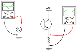
It should be apparent that only portions of the input are being reproduced at the output of this circuit. The rest of the waveform seems to be “missing,” being replaced by a flat line. Explain why this transistor circuit is not able to amplify the entire waveform.
Reveal answerTransistors are essentially DC devices, not AC devices. Consider the base-emitter PN junction that the input signal is sent to: it can only conduct in one direction (base positive and emitter negative).
Notes:Sometimes it is helpful for students to re-draw the circuit using a transistor model showing the base-emitter junction as a diode. If you think this model would help some of your students understand the concept here, have another student draw the transistor model on the whiteboard, and use that drawing as a discussion aid. Like any PN junction, the base-emitter junction of a BJT only “wants” to conduct current in one direction.
-
Question 6 of 21
Class-A operation may be obtained from this simple transistor circuit if the input voltage (Vin) is “biased” with a series-connected DC voltage source:
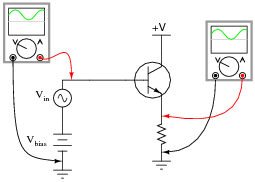
First, define what “Class A” amplifier operation is. Then, explain why biasing is required for this transistor to achieve it.
Reveal answer“Class A” amplifier operation is when the transistor remains in its “active” mode (conducting current) throughout the entire waveform. Biasing may be thought of as a kind of “trick” used to get the transistor (a DC device) to “think” it is amplifying DC when the input signal is really AC.
Notes:A “trick” it may be, but a very useful and very common “trick” it is! Discuss this concept with your students at length, being sure they have ample time and opportunity to ask questions of their own.
One question that may arise is, “how much DC bias voltage is necessary?” If no one asks this question, ask it yourself! Discuss with your students what would constitute the minimum amount of bias voltage necessary to ensure the transistor never goes into “cutoff” anywhere in the waveform’s cycle, and also the maximum bias voltage to prevent the transistor from “saturating”.


