Facebook
 Google
 GitHub
 Linkedin
Discrete Semiconductor Devices and Circuits
Bipolar Transistor Biasing Circuits
21 questions By Tony R. Kuphaldt
-
Question 16 of 21
Calculate the approximate quiescent (DC) base current for this transistor circuit, assuming an AC input voltage of 0 volts, and a silicon transistor:

Reveal answerIB = 38.3 μA
Notes:This circuit was purposely drawn in a convoluted fashion to force students to identify its configuration apart from the standard layout. Many people lack the spatial reasoning skills to do this easily, and require a lot of practice before they become proficient. Ask your more proficient students if they have any “tips” for helping those who struggle with problems like these. Are there any simple methods which we may use to re-draw this circuit in an easier-to-understand form?
-
Question 17 of 21
Calculate the potentiometer wiper voltage (Vbias) required to maintain the transistor right at the threshold between cutoff and active mode. Then, calculate the input voltage required to drive the transistor right to the threshold between active mode and saturation. Assume ideal silicon transistor behavior, with a constant β of 100:

Reveal answerAt the threshold between cutoff and active mode, Vbias = -0.7 volts
At the threshold between active mode and saturation, Vbias = -1.72 volts (assuming 0 volts VCE at saturation)
Follow-up question: if we were using the potentiometer to establish a bias voltage for an AC signal, what amount of DC bias voltage would place the transistor directly between these two extremes of operation (cutoff versus saturation), so as to allow the AC input signal to “swing” equal amounts positive and negative at the distortion limit? In other words, what voltage setting is exactly between -0.7 volts and -1.72 volts?
Notes:If your students are experiencing difficulty analyzing this circuit, ask them to begin by calculating the transistor currents at the thresholds of cutoff and saturation.
A mathematical trick I’ve found helpful through the years for finding the midpoint between two values is to add the two values together and then divide by two. Challenge your students to use other means of calculating this midpoint value, though.
-
Question 18 of 21
When inserting a signal coupling capacitor into the bias network for this transistor amplifier, which way should the (polarized) capacitor go? (Hint: the AC signal source outputs pure AC, with a time-averaged DC value of 0 volts).

Explain why the orientation of this capacitor matters, and what might happen if it is connected the wrong way.
Reveal answer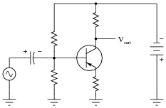
Notes:It is easy to miss the detail of the power supply’s polarity being “backward” from what is typically seen (negative instead of positive). Actually, I am surprised to see how many introductory textbooks have the coupling capacitor drawn the wrong way, so expect that some students may become confused by researching their texts for the answer!