
 Facebook
 Google
 GitHub
 Linkedin
Discrete Semiconductor Devices and Circuits
Bipolar Transistor Biasing Circuits
21 questions By Tony R. Kuphaldt
-
Question 10 of 21
Class-A operation may be obtained from this simple transistor circuit if the input voltage (Vin) is “biased” with a series-connected DC voltage source:
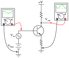
First, define what “Class A” amplifier operation is. Then, explain why biasing is required for this transistor to achieve it.
Reveal answer“Class A” amplifier operation is when the transistor remains in its “active” mode (conducting current) throughout the entire waveform. Biasing may be thought of as a kind of “trick” used to get the transistor (a DC device) to “think” it is amplifying DC when the input signal is really AC.
Notes:A “trick” it may be, but a very useful and very common “trick” it is! Discuss this concept with your students at length, being sure they have ample time and opportunity to ask questions of their own.
One question that may arise is, “how much DC bias voltage is necessary?” If no one asks this question, ask it yourself! Discuss with your students what would constitute the minimum amount of bias voltage necessary to ensure the transistor never goes into “cutoff” anywhere in the waveform’s cycle, and also the maximum bias voltage to prevent the transistor from “saturating”.
-
Question 11 of 21
Explain how the following bias networks function:

Each one has the same basic purpose, but works in a different way to accomplish it. Describe the purpose of any biasing network in an AC signal amplifier, and comment on the different means of accomplishing this purpose employed by each of the three circuits.
Reveal answerThe purpose of any biasing network in an AC signal amplifier is to provide just enough quiescent current through the base to keep the transistor between the extremes of cutoff and saturation throughout the input signal’s waveform cycle.
Notes:All three biasing techniques are commonly used in transistor amplifier circuitry, so it behooves each student to understand them well. In each case, resistors provide a “trickle” of current through the base of the transistor to keep it turned partially “on” at all times.
-
Question 12 of 21
A very common method of providing bias voltage for transistor amplifier circuits is with a voltage divider:

However, if we were to directly connect a source of AC signal voltage to the junction between the two voltage divider resistors, the circuit would most likely function as if there were no voltage divider network in place at all:

Instead, circuit designers usually place a coupling capacitor between the signal source and the voltage divider junction, like this:
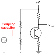
Explain why a coupling capacitor is necessary to allow the voltage divider to work in harmony with the AC signal source. Also, identify what factors would be relevant in deciding the size of this coupling capacitor.
Reveal answerA very good way to understand the AC source’s effect on the voltage divider with and without the capacitor is to use Superposition Theorem to determine what each source (AC signal, and DC power supply) will do separately.
If this concept is still not clear, consider this circuit:

As far as capacitor size is concerned, it should be large enough that its reactance is negligible. I’ll let you determine what factors define negligibility in this context!
Follow-up question: which voltage source (AC or DC?) “wins” at the point specified in the above circuit? Explain why this is so, and then show how a suitably located capacitor would allow both voltage signals to co-exist at that point.
Notes:Many beginning students experience difficulty understanding the purpose of the coupling capacitor, and transistor amplifier biasing in general. Be sure to spend plenty of time discussing the principle of this circuit, because it is very commonplace in transistor circuitry.


