
 Facebook
 Google
 GitHub
 Linkedin
Digital Circuits
Boolean Algebra
67 questions By Tony R. Kuphaldt
-
Question 19 of 67
An engineer hands you a piece of paper with the following Boolean expression on it, and tells you to build a gate circuit to perform that function:
$$A\overline{B}+\overline{C}(A+B)$$
Draw a logic gate circuit for this function.
Reveal answer
Notes:The process of converting Boolean expressions into logic gate circuits is not quite as simple as converting gate circuits into Boolean expressions, but it is manageable. Have your students share whatever methods or “tricks” they use to write the expressions with the rest of the class.
-
Question 20 of 67
A critical electronic system receives DC power from three power supplies, each one feeding through a diode, so that if one power supply develops an internal short-circuit, it will not cause the others to overload:
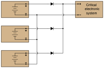
The only problem with this system is that we have no indication of trouble if just one or two power supplies do fail. Since the diode system routes power from any available supply(ies) to the critical system, the system sees no interruption in power if one or even two of the power supplies stop outputting voltage. It would be nice if we had some sort of alarm system installed to alert the technicians of a problem with any of the power supplies, long before the critical system was in jeopardy of losing power completely.
An engineer decides that a relay could be installed at the output of each power supply, prior to the diodes. Contacts from these relays could then be connected to some sort of alarm device (flashing light, bell, etc.) to alert maintenance personnel of any problem:
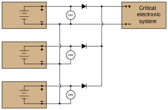
Part 1: Draw a ladder diagram of the relay contacts powering a warning lamp, in such a way that the lamp energizes if any one or more of the power supplies loses output voltage. Write the corresponding Boolean expression for this circuit, using the letters A, B, and C to represent the status of relay coils CR1, CR2, and CR3, respectively.
Part 2: The solution to Part 1 worked, but unfortunately it generated “nuisance alarms” whenever a technician powered any one of the supplies down for routine maintenance. The engineer decides that a two-out-of-three-failed alarm system will be sufficient to warn of trouble, while allowing for routine maintenance without creating unnecessary alarms. Draw a ladder diagram of the relay contacts powering a warning lamp, such that the lamp energizes if any two or more power supplies lose output voltage. The Boolean expression for this is \(\overline{A} \ \overline{B}+\overline{B} \ \overline{C} + \overline{A} \ \overline{C}\).
Part 3: Management at this facility changed their minds regarding the safety of a two-out-of-three-failed alarm system. They want the alarm to energize if any one of the power supplies fails. However, they also realize that nuisance alarms generated during routine maintenance are unacceptable as well. Asking the maintenance crew to come up with a solution, one of the technicians suggests inserting a “maintenance” switch that will disable the alarm during periods of maintenance, allowing for any of the power supplies to be powered down without creating a nuisance alarm. Modify the alarm circuit of part 1’s solution to include such a switch, and correspondingly modify the Boolean expression for the new circuit (call the maintenance switch M).
Part 4: During one maintenance cycle, a technician accidentally left the alarm bypass switch (M) actuated after he was done. The system operated with the power failure alarm disabled for weeks. When management discovered this, they were furious. Their next suggestion was to have the bypass switch change the conditions for alarm, such that actuating this “M” switch would turn the system from a one-out-of-three-failed alarm into a two-out-of-three-failed alarm. This way, any one power supply may be taken out of service for routine maintenance, yet the alarm will not be completely de-activated. The system will still alarm if two power supplies were to fail. The simplified Boolean expression for this rather complex function is \(\overline{A} \ \overline{B}+\overline{C} \ \overline{M} + (\overline{A} \ +\overline{B})+ (\overline{C} \ +\overline{M})\). Draw a ladder diagram for the alarm circuit based on this expression.
Reveal answerPart 1 solution:

Part 2 solution:

Part 3 solution:

Part 4 solution:

Follow-up question: how many contacts on each relay (and on the maintenance switch “M”) are necessary to implement any of these alarm functions?
Challenge question: can you see any way we could reduce the number of relay contacts necessary in the circuit of solutions 2, yet still achieve the same logic functionality (albeit with a different Boolean expression)?
Notes:To be honest, I had fun writing the scenarios for different parts of this problem. The evolution of this alarm system is typical for an organization. Someone comes up with an idea, but it doesn’t meet all the needs of someone else, so they input their own suggestions, and so on, and so on. Presenting scenarios such as this not only prepare students for the politics of real work, but also underscore the need to “what if?” thinking: to test the proposed solution before implementing it, so that unnecessary problems are avoided.
-
Question 21 of 67
Implement the following Boolean expression in the form of a digital logic circuit:
$$\overline{(\overline{AB}+C)}B$$
Form the circuit by making the necessary connections between pins of these integrated circuits on a solderless breadboard:

Reveal answerThe circuit shown is not the only possible solution to this problem:

Notes:First things first: did students remember to include the power supply connections to each IC? This is a very common mistake!
In order to successfully develop a solution to this problem, of course, students must research the “pinouts” of each integrated circuit. If most students simply present the answer shown to them in the worksheet, challenge them during discussion to present alternative solutions.
Also, ask them this question: “should we connect the unused inputs to either ground or VCC, or is it permissible to leave the inputs floating?” Students should not just give an answer to this question, but be able to support their answer(s) with reasoning based on the construction of this type of logic circuit.






Question 29, answer 3 has a typo - should be A*B + !(D)*E not A*B+!(D*E)