Facebook
 Google
 GitHub
 Linkedin
Analog Integrated Circuits
Inverting and Noninverting OpAmp Voltage Amplifier Circuits
41 questions By Tony R. Kuphaldt
-
Question 25 of 41
Calculate the necessary resistor value (R1) in this circuit to give it a voltage gain of 7.5:

Reveal answerR1 = 62.25 kΩ
Notes:Ask your students how they solved this problem, especially since it is fairly safe to say that they didn’t find the equation directly solving for R1 in any book. Algebraic manipulation is necessary to take the standard voltage gain equation and put it into a form suitable for use answering this question.
-
Question 26 of 41
Predict how the operation of this operational amplifier circuit will be affected as a result of the following faults. Consider each fault independently (i.e. one at a time, no multiple faults):

- Resistor R1 fails open:
- Solder bridge (short) across resistor R1:
- Resistor R2 fails open:
- Solder bridge (short) across resistor R2:
- Broken wire between R1/R2 junction and inverting opamp input:
For each of these conditions, explain why the resulting effects will occur.
Reveal answer- Resistor R1 fails open: Vout = 0 volts.
- Solder bridge (short) across resistor R1: Output saturates negative.
- Resistor R2 fails open: Output saturates negative.
- Solder bridge (short) across resistor R2: Vout = 0 volts.
- Broken wire between R1/R2 junction and inverting opamp input: Output voltage unpredictable.
Notes:The purpose of this question is to approach the domain of circuit troubleshooting from a perspective of knowing what the fault is, rather than only knowing what the symptoms are. Although this is not necessarily a realistic perspective, it helps students build the foundational knowledge necessary to diagnose a faulted circuit from empirical data. Questions such as this should be followed (eventually) by other questions asking students to identify likely faults based on measurements.
-
Question 27 of 41
There is something wrong with this amplifier circuit. Note the relative amplitudes of the input and output signals as measured by an oscilloscope:
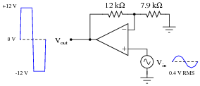
This circuit used to function perfectly, but then began to malfunction in this manner: producing a “clipped” output waveform of excessive amplitude. Determine the approximate amplitude that the output voltage waveform should be for the component values given in this circuit, and then identify possible causes of the problem and also elements of the circuit that you know cannot be at fault.
Reveal answerVout (ideal) = 1.01 volts RMS
I’ll let you determine possible faults in the circuit! From what we see here, we know the power supply is functioning (both V and -V rails) and that there is good signal getting to the non-inverting input of the opamp.
Notes:There is definitely more than one possible cause for the observed problem. Discuss alternatives with your students, involving them in the diagnosis process. Ask them why we know that certain elements of the circuit are functioning as they should? Of the possible causes, which are more likely, and why?