Facebook
 Google
 GitHub
 Linkedin
Analog Integrated Circuits
Inverting and Noninverting OpAmp Voltage Amplifier Circuits
41 questions By Tony R. Kuphaldt
-
Question 34 of 41
Predict how the input impedance (Zin) of this inverting operational amplifier circuit will be affected as a result of the following faults. Consider each fault independently (i.e. one at a time, no multiple faults):

- Resistor R1 fails open:
- Solder bridge (short) across resistor R1:
- Resistor R2 fails open:
- Solder bridge (short) across resistor R2:
- Broken wire between R1/R2 junction and inverting opamp input:
- Operational amplifier loses power:
For each of these conditions, explain why the input impedance changes as it does.
Reveal answer- Resistor R1 fails open: Zin increases to infinity.
- Solder bridge (short) across resistor R1: Zin decreases to (nearly) zero.
- Resistor R2 fails open: Zin increases to (nearly) infinity.
- Solder bridge (short) across resistor R2: Zin remains equal in value to R1, as normal.
- Broken wire between R1/R2 junction and inverting opamp input: Zin increases to (approximately) R1 R2.
- Operational amplifier loses power: Zin increases to (nearly) infinity.
Notes:The purpose of this question is to approach the domain of circuit troubleshooting from a perspective of knowing what the fault is, rather than only knowing what the symptoms are. Although this is not necessarily a realistic perspective, it helps students build the foundational knowledge necessary to diagnose a faulted circuit from empirical data. Questions such as this should be followed (eventually) by other questions asking students to identify likely faults based on measurements.
-
Question 35 of 41
Calculate the voltage gain for each stage of this amplifier circuit (both as a ratio and in units of decibels), then calculate the overall voltage gain:
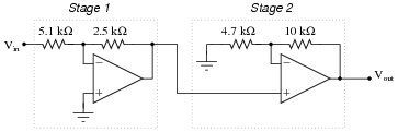
Reveal answer- Stage 1:
- AV = 0.490 = -6.193 dB
- Stage 2:
- AV = 3.128 = 9.904 dB
- Overall:
- AV = 1.533 = 3.712 dB
Follow-up question: is this circuit inverting or non-inverting, overall?
Notes:Not only does this question review calculation of voltage gain for inverting amplifier circuits, but it also reviews decibel calculations (for both single and multi-stage amplifiers). Discuss how the decibel figures for each stage add to equal the total decibel gain, whereas the ratios multiply.
-
Question 36 of 41
Shown here are two different voltage amplifier circuits with the same voltage gain. Which of them has greater input impedance, and why? Try to give as specific an answer for each circuit’s input impedance as possible.

Reveal answerThe non-inverting amplifier circuit has extremely high input impedance (most likely many millions of ohms), while the inverting amplifier circuit only has 5 kΩ of input impedance.
Notes:If students have difficulty grasping the concept of input impedance, and how to figure that out for circuits such as these, remind them that input impedance is fundamentally defined by the following equation:
Zin = Vin IinWith this in mind, encourage them to set up a “thought experiment” by where they assume a given input voltage and analyze the circuit step-by-step using Ohm’s Law, Kirchhoff’s Laws, and the basic rules of closed-loop, negative feedback opamp behavior. The results of the “thought experiment” should conclusively demonstrate which circuit has the greater input impedance.