Facebook
 Google
 GitHub
 Linkedin
Analog Integrated Circuits
Inverting and Noninverting OpAmp Voltage Amplifier Circuits
41 questions By Tony R. Kuphaldt
-
Question 37 of 41
A simple “follower” circuit that boosts the current-output ability of this non-inverting amplifier circuit is a set of bipolar junction transistors, connected together in a “push-pull” fashion like this:

However, if connected exactly as shown, there will be a significant voltage error introduced to the opamp’s output. No longer will the final output voltage (measured across the load) be an exact 3:1 multiple of the input voltage, due to the 0.7 volts dropped by the transistor in active mode:
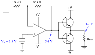
There is a very simple way to completely eliminate this error, without adding any additional components. Modify the circuit accordingly.
Reveal answer
If you understand why this circuit works, pat yourself on the back: you truly understand the self-correcting nature of negative feedback. If not, you have a bit more studying to do!
Notes:The answer is not meant to be discouraging for those students of yours who do not understand how the solution works. It is simply a “litmus test” of whether or not your students really comprehend the concept of negative feedback. Although the change made in the circuit is simple, the principle is a bit of a conceptual leap for some people.
It might help your students understand if you label the new wire with the word sense, to indicate its purpose of providing feedback from the very output of the circuit, back to the opamp so it can sense how much voltage the load is receiving.
-
Question 38 of 41
A student wishes to build a variable-gain amplifier circuit using an operational amplifier and a potentiometer. The purpose of this circuit is to act as an audio amplifier for a small speaker, so he can listen to the output of a digital audio player without having to use headphones:
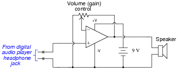
Before building the project in a finalized form, the student prototypes it on a solderless breadboard to make sure it functions as intended. And it is a good thing he decided to do this before wasting time on a final version, because it sounds terrible!
When playing a song, the student can hear sound through the headphones, but it is terribly distorted. Taking the circuit to his instructor for help, the instructor suggests the following additions:
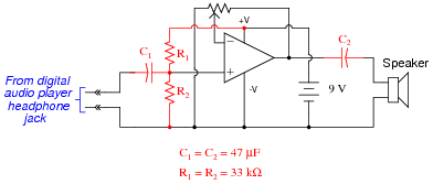
After adding these components, the circuit works great. Now, music may be heard through the speaker with no noticeable distortion.
Explain what functions the extra components perform, and why the circuit did not work as originally built.
Reveal answerThe output of the audio player is true AC (alternating positive and negative polarity), but the original circuit could only handle input voltages ranging from 0 volts to V, nothing negative.
Notes:This question illustrates a common problem in opamp circuit design and usage: it is easy for students to overlook the importance of considering the power supply rail voltages. Despite the fact that the rails are labeled “ V” and “-V” at the opamp chip terminals, the input signal is actually referenced to the negative side of the power supply, which means that every negative half-cycle of the input voltage goes beyond the -V power supply rail voltage, and the opamp cannot handle that.
The instructor’s solution to this problem should look very similar to voltage divider biasing in a single-transistor circuit, providing a good opportunity to review that concept with your students.
Some students may ask where the second speaker is, for stereo sound. If they do, tell them that this circuit only represents one channel’s worth of amplification, and that the other channel’s circuit would look just the same. If a single volume control were desired to control the gain of both amplifier circuits, a dual-ganged potentiometer could be used (another point of discussion for your students!).
-
Question 39 of 41
There is something wrong with this amplifier circuit. Despite an audio signal of normal amplitude detected at test point 1 (TP1), there is no output measured at the Äudio signal out” jack:
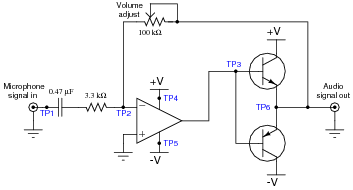
Next, you decide to check for the presence of a good signal at test point 3 (TP3). There, you find 0 volts AC and DC no matter where the volume control is set.
From this information, formulate a plan for troubleshooting this circuit, answering the following questions:
- What type of signal would you expect to measure at TP3?
- What would be your next step in troubleshooting this circuit?
- Are there any elements of this circuit you know to be working properly?
- What do you suppose would be the most likely failure, assuming this circuit once worked just fine and suddenly stopped working all on it’s own?
Reveal answerThe correct voltage signal at TP3 should be an audio waveform with significant crossover distortion (specifically, a vertical “jump” at each point where the waveform crosses zero volts, about 1.4 volts peak to peak). I’ll let you figure out answers to the other questions on your own, or with classmates.
Notes:I have found that troubleshooting scenarios are always good for stimulating class discussions, with students posing strategies for isolating the fault(s) and correcting one another on logical errors. There is not enough information given in this question to ensure a single, correct answer. Discuss this with your students, helping them to use their knowledge of circuit theory and opamps to formulate good diagnostic strategies.