Facebook
 Google
 GitHub
 Linkedin
AC Electric Circuits
Mutual Inductance
12 questions By Tony R. Kuphaldt
-
Question 10 of 12
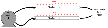
Mutual inductance can exist even in places where we would rather it not. Take for instance the situation of a “heavy” (high-current) AC electric load, where each conductor is routed through its own metal conduit. The oscillating magnetic field around each conductor induces currents in the metal conduits, causing them to resistively heat (Joule’s Law, P = I2 R):
It is standard industry practice to avoid running the conductors of a large AC load in separate metal conduits. Rather, the conductors should be run in the same conduit to avoid inductive heating:
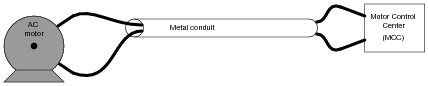
Explain why this wiring technique eliminates inductive heating of the conduit.
Now, suppose two empty metal conduits stretch between the location of a large electric motor, and the motor control center (MCC) where the circuit breaker and on/off “contactor” equipment is located. Each conduit is too small to hold both motor conductors, but we know we’re not supposed to run each conductor in its own conduit, lest the conduits heat up from induction. What do we do, then?

Reveal answerUse terminal blocks to “split up” the conductors from one pair into two pairs:

Notes:This wiring technique is very commonly used in industry, where conductor gauges for high-horsepower electric motors can be quite large, and conduits never quite large enough.
-
Question 11 of 12
Suppose a technician needs 167 mH of inductance in a circuit, but only has 500 mH and 250 mH inductors on hand. He decides he should be able to achieve approximately 167 mH of inductance easily enough by connecting these two inductors in parallel with one another on a printed circuit board:
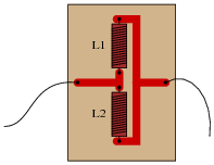
However, upon testing this parallel inductor arrangement, the technician finds the total inductance to be significantly less than the 167 mH predicted. Puzzled, he asks a fellow technician for help. The other technician inspects the board, and immediately suggests that the two inductors be re-located with their axes perpendicular to one another. The first technician doesn’t understand why the physical location of the inductors should matter. After all, it never mattered how he located resistors and capacitors with respect to one another, so long as their connecting wires (or board traces) went to the right places. Can you explain to him why inductors might be sensitive to physical orientation?
Reveal answerPresently, the respective magnetic fields from the two inductors are linking with each other in an opposing manner!
Follow-up question: coils placed in linear proximity to one another will magnetically “link” in such a way as to either “boost” (Figure A) or “buck” (Figure B) one another. If placed perpendicular (90o) to one another, the magnetic linking is nonexistent and the two inductors act as independent entities:

What trigonometric function (sine, cosine, tangent, cotangent, secant, cosecant) follows this same pattern: full positive at 0o, full negative at 180o, and zero at 90o?
Notes:A potential point of confusion here is that some students may think the orientation being spoken of is absolute: with reference to the earth’s magnetic field. What I’m trying to get them to see, however, is the relationship between the two coils’ magnetic fields, which is an entirely different matter. To expose this misunderstanding, ask your students whether or not the position of the printed circuit board with respect to compass directions (north, south, east, or west) would have any effect on these two inductors’ combined inductance. For those who mistakenly answer “yes” to this question, review Faraday’s Law of electromagnetic induction: that induced voltage only occurs when there is a change of magnetic flux over time, and that the earth’s magnetic field is constant (for all practical purposes).
The follow-up question gets students thinking in terms of the mutual inductance as a function of the physical angle between the two inductors, and relating a pattern (analyzed at three points) to common trig functions. This form of reasoning is very useful in problem-solving, because the ability to see patterns as a function of a certain variable (such as an angle) is the first step in mathematically modeling a system.
-
Question 12 of 12
Explain what leakage inductance is, in a system of two or more mutually coupled inductors (such as a transformer). In a transformer, is leakage inductance a good thing or a bad thing?
Reveal answer“Leakage inductance” is inductance that is not mutual between coupled inductors. It is caused by magnetic flux produced by one coil that does not “link” with turns of the other coil(s).
In power distribution transformers, leakage inductance is undesirable. However, there are some applications where leakage inductance is a desirable attribute. Step-up transformers used to power gas-discharge lights, for example, are purposely built to have significant amounts of leakage inductance.
Notes:After discussing the nature of leakage inductance (what causes it, and how it manifests itself in a transformer circuit), ask your students to explain why we do not want to have leakage inductance in a power distribution transformer, and why we do want to have it in a gas-discharge lighting transformer.