
 Facebook
 Google
 GitHub
 Linkedin
AC Electric Circuits
Oscilloscope Trigger Controls
15 questions By Tony R. Kuphaldt
-
Question 7 of 15
A student is experimenting with an oscilloscope, learning how to use the triggering control. While turning the trigger level knob clockwise, the student sees the effect it has on the waveform’s position on the screen. Then, with an additional twist of the level knob, the waveform completely disappears. Now there is absolutely nothing shown on the screen! Turning the level knob the other way (counter-clockwise), the waveform suddenly appears on the screen again.
Based on the described behavior, does this student have the oscilloscope trigger control set on Auto mode, or on Norm mode? What would the oscilloscope do if the other triggering mode were set?
Reveal answerThis student’s oscilloscope is set on the Norm mode. If it were set on the Auto mode, the trace would default to “free-running” if ever the trigger level were set above or below the waveform’s amplitude. Instead of completely disappearing, the waveform would scroll horizontally and not “stand still” if the trigger level were set too high or too low.
Notes:Ask your students to explain which mode they think the oscilloscope should ordinarily be set in for general-purpose use.
-
Question 8 of 15
How will the oscilloscope trigger if the control is set to Line source rather than A or B inputs:
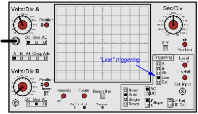
Reveal answerIn this mode, the oscilloscope triggers off the power-line waveform.
Follow-up question: what circumstance can you think of that would require this triggering source?
Notes:“Line” triggering is a very useful feature, especially for working on line-powered and line-synchronized circuits. SCR- and TRIAC-based motor control circuits come immediately to mind here, as do brute-force (linear) power supply circuits!
-
Question 9 of 15
Large electric motors and other pieces of rotating machinery are often equipped with vibration sensors to detect imbalances. These sensors are typically linked to an automatic shutdown system so that the machine will turn itself off it the sensors detect excessive vibration.
Some of the more popular industrial-grade sensors generate a DC voltage proportional to the physical distance between the end of the sensor and the nearest metallic surface. A typical sensor installation might look like this:

If the machine is running smoothly (or if it is shut down and not turning at all), the output voltage from the sensor will be pure DC, indicating a constant distance between the sensor end and the shaft surface. On the other hand, if the shaft becomes imbalanced it will bend ever so slightly, causing the distance to the sensor tip to periodically fluctuate as it rotates beneath the sensor. The result will be a sensor output signal that is an AC “ripple” superimposed on a DC bias, the frequency of that ripple voltage being equal to the frequency of the shaft’s rotation:

The vibration sensing circuitry measures the amplitude of this ripple and initiates a shutdown if it exceeds a pre-determined value.
An additional sensor often provided on large rotating machines is a sync pulse sensor. This sensor works just like the other vibration sensors, except that it is intentionally placed in such a position that it “sees” a keyway or other irregularity on the rotating shaft surface. Consequently, the “sync” sensor outputs a square-wave “notch” pulse, once per shaft revolution:
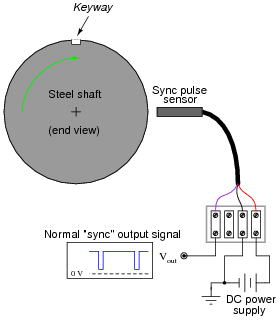
The purpose of this “sync” pulse is to provide an angular reference point, so any vibration peaks seen on any of the other sensor signals may be located relative to the sync pulse. This allows a technician or engineer to determine where in the shaft’s rotation any peaks are originating.
Your question is this: explain how you would use the sync pulse output to trigger an oscilloscope, so that every sweep of the electron beam across the oscilloscope’s screen begins at that point in time.
Reveal answerConnect the “sync” pulse output to the “External Input” connector on the oscilloscope’s front panel, and set the trigger source accordingly:

Notes:There are many electronic (non-mechanical) examples one could use to illustrate the use of external triggering. I like to introduce something like this once in a while to broaden students’ thoughts beyond the world of tiny components and circuit boards. The practical applications of electronics are legion!








response are clear, thank you