
 Facebook
 Google
 GitHub
 Linkedin
Digital Circuits
Shift Registers
22 questions By Tony R. Kuphaldt
-
Question 16 of 22
A binary number is parallel-loaded into a shift register. The shift register is then commanded to “shift right” for one clock pulse. How does the value of the shifted binary number compare to the number originally loaded in, assuming that the MSB is on the very left flip-flop of the shift register?
Reveal answerThe new binary number value will be one-half (or approximately one-half) the value that it was before.
Follow-up question: how could we use the shift register to double the value of a binary number?
Challenge question: when we divide a binary number in two by shifting its bit positions, the resulting answer may or may not be exactly one-half the original value. Explain why this is so. Also, analyze what happens when when we multiply a binary number by two through a process of bit-shifting. Is the resulting answer exactly twice the original value, or may it also be approximate as it sometimes is with division? Explain why or why not.
Notes:This is a really neat trick for dividing or multiplying binary numbers by powers of two. It is often used in machine-language microprocessor programming, due to its simplicity of execution.
-
Question 17 of 22
Switch contact bounce is often a problem when connecting mechanical contact switches or relays to the inputs of digital semiconductor circuits. When a switch transitions from open to closed, or from closed to open, there is usually a burst of on/off pulses rather than a single, crisp, change of logic state:
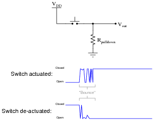
Digital electronic circuits, of course, react to these pulses as though they were very rapid actuations/de-actuations of the switch. This may cause problems, especially in applications where a mechanical switch input causes a counter to increment or decrement!
To fix this problem we must properly condition the switch signal to eliminate the spurious on/off pulses. The process of doing this is called debouncing. There is more than one way to de-bounce a switch, but one of the more sophisticated ways uses a serial-in, serial-out shift register with an asynchronous reset (clear) input:

Explain how this circuit works to de-bounce the switch’s “dirty” signal, producing a “clean” (de-bounced) signal for a subsequent digital circuit’s input.
Reveal answerThe “de-bounced” output line will go high only when the switch signal has been continuously high for at least four clock pulses.
Follow-up question #1: which switch (input) transition is seen immediately at the output, a low-to-high transition or a high-to-low transition?
Follow-up question #2: does this circuit de-bounce a noisy low-to-high switch (input) transition, a noisy high-to-low switch transition, or both?
Follow-up question #3: does the pushbutton switch source or sink current in this circuit?
Challenge question: how would you go about selecting an appropriate clock frequency for this circuit?
Notes:Some students may need to see a pulse diagram for this circuit before they fully grasp how it functions. If so, have students come up to the board in the front of the room and work through an analysis of it rather than doing it yourself.
Not only does this question review shift register operation, but it also reviews the problem of switch contact bounce and showcases a practical solution for it. Incidentally, this question provides a good excuse for a hands-on demonstration of switch bounce using the switch/pulldown circuit first shown and a digital storage oscilloscope to capture the switching action. Students are likely to be surprised by just how “dirty” the switch signal is!
-
Question 18 of 22
A mechanically inclined friend of yours wishes to build an automated water fountain, where ten water jets are turned on in sequence, one at a time. Each water jet is controlled by a solenoid valve, energized by 120 volt AC line power.
Your friend understands how to wire up the solenoid valves and build all the plumbing to make the fountain work. He also understands how to interpose power to the solenoid valve coils using small relays, so a digital control circuit operating at a low DC supply voltage will be able to energize the valves. The only problem is, this friend of yours does not know how to build a circuit to do the sequencing. How do you turn on one out of ten outputs at a time, in sequence?
Another friend who is studying digital circuits has a solution to the design problem. She says you could generate a one-out-ten sequence by using a BCD counter (4 bit) driving a 4-line to 16-line decoder. A simple 555 astable multivibrator circuit could supply the necessary clock pulses, and the decoder outputs could drive the relays, and then the solenoid valves, as fast as you wanted.
However, your instructor just recently told you about a different way to generate a one-out-of-n counting sequence by using shift registers: the circuit is called a ring counter. A ring counter would use fewer parts than the counter/decoder idea. Explain what a ring counter is, and how it would work in this application.
Reveal answerRing counter circuits are simple enough to not require my elaboration. The only tough part of this design problem might be in achieving the initial “high” state in the first bit of the shift register upon power-up. The rest is child’s play!
Notes:Actually, this question would make a great class project for your students to build. Not just the ring counter itself, but all the power supply and power control circuitry as well. I’ve actually had a student team build a programmable ornamental fountain before, using a microcontroller. We entered it as a piece of kinetic artwork in a campus art show, and it was a hit (especially for young children playing in the water jets on a hot day). It was a lot of fun and the students learned a lot!



any one can help me