
 Facebook
 Google
 GitHub
 Linkedin
AC Electric Circuits
AC Motor Control Circuits
23 questions By Tony R. Kuphaldt
-
Question 16 of 23
Interpret this AC motor control circuit diagram, explaining the meaning of each symbol:
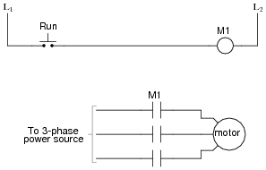
Also, explain the operation of this motor control circuit. What happens when someone actuates the “Run” switch? What happens when they let go of the “Run” switch?
Reveal answerThe “Run” switch is a normally-open pushbutton. Relay coil “M1” is energized by this switch, and actuates three normally-open contacts (also labeled “M1”) to send three-phase power to the motor. Note that the details of the power supply are not shown in these diagrams. This is a common omission, done for the sake of simplicity.
Notes:Discuss with your students the sources of electrical power for both circuits here: the relay control circuit and the motor itself. Challenge your students to explore this concept by asking them the following questions:
- • Are the two sources necessarily the same?
- • How does the convention of linking relay coils with contacts by name (rather than by dashed lines and proximity) in ladder diagrams benefit multiple-source circuits such as this one?
- • Do these circuits even have to be drawn on the same page?
-
Question 17 of 23
Identify at least one fault that would cause the motor to turn off immediately once the “Start” pushbutton switch was released, instead of “latch” in the run mode as it should:

For each of your proposed faults, explain why it will cause the described problem.
Reveal answer- • M1 control contact failed open.
- • Wire(s) between M1 control contact and control circuit broken open.
Notes:This form of motor control circuit is very popular in industry. It is well worth your students’ time to study it and understand both how and why it works.
-
Question 18 of 23
A very common form of latch circuit is the simple “start-stop” relay circuit used for motor controls, whereby a pair of momentary-contact pushbutton switches control the operation of an electric motor. In this particular case, I show a low-voltage control circuit and a 3-phase, higher voltage motor:

Explain the operation of this circuit, from the time the “Start” switch is actuated to the time the “Stop” switch is actuated. The normally-open M1 contact shown in the low-voltage control circuit is commonly called a seal-in contact. Explain what this contact does, and why it might be called a “seal-in” contact.
Reveal answerEven though the “Start” and “Stop” switches are momentary, the “seal-in” contact makes the circuit latch in one of two states: either motor energized or motor de-energized.
Notes:Motor “start-stop” circuits are very common in industry, and apply to applications beyond electric motors. Ask your students if they can think of any application for a circuit such as this.






Hello, sir.
Please share the name of the Source material/ Text book used in this Article. I will be very thankful to you.
Thanks for doing such a great job.
Good day.
Please I’m Benjamin Akrofi and I need answers to question 8
The name of the site I saw the question is ALL ABOUT CIRCUITS