
 Facebook
 Google
 GitHub
 Linkedin
AC Electric Circuits
AC Motor Control Circuits
23 questions By Tony R. Kuphaldt
-
Question 13 of 23
There are several different methods of providing reduced-voltage starting for electric motors. One of them is the autotransformer method. Here is a diagram showing how this works:

“L1,” “L2,” and “L3” represent the three phase power supply conductors. Three sets of contacts (R, S, and Y) serve to connect power to the motor at different times. The starting sequence for the motor is as follows:
- 1. Motor off (R open, S open, Y open)
- 2. Start button pressed (S and Y contacts all close)
- 3. Time delay (depending on the size of the motor)
- 4. Y contacts open
- 5. Time delay (depending on the size of the motor)
- 6. R contacts close, S contacts open
Explain the operation of this system. How do the autotransformers serve to reduce voltage to the electric motor during start-up?
Reveal answerWhen the “S” and “Y” contacts are all closed, the autotransformers form a three-phase “Y” connection, with line voltage (L1, L2, and L3) applied to the “tips” of the “Y,” and a reduced motor voltage tapped off a portion of each autotransformer winding.
When the “Y” contacts open, the three autotransformers now function merely as series-connected inductors, limiting current with their inductive reactance.
When the “R” contacts close, the motor receives direct power from L1, L2, and L3.
Follow-up question: how do the overload heaters function in this circuit? They aren’t connected in series with the motor conductors as is typical with smaller motors!
Notes:For each step of the start-up sequence, it is possible to re-draw the circuit feeding power to the motor, in order to make its function more apparent. Do not create these re-drawings yourself, but have your students draw an equivalent circuit for each step in the start-up sequence.
The follow-up question is a good review of current transformers (CT), as well as an introduction to the use of overload heaters in high-current electrical systems.
-
Question 14 of 23
Identify at least three independent faults that could cause this motor not to start:
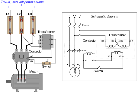
For each of the proposed faults, explain why they would prevent the motor from starting.
Reveal answerHere are some possible faults (not an exhaustive list by any means!):
- • Any fuse blown
- • Contactor coil failed open
- • Any transformer winding failed open
- • Broken jumper between H3 and H2 on the transformer
- • Corroded wire connection at terminal A1 or A2
- • Motor winding failed shorted
Follow-up question: there will be a difference in operation between the L1 fuse blowing and either the L2 or L3 fuse blowing. Explain what this difference is, and why it might serve as a clue to what was wrong.
Notes:Identifying multiple faults should be quite easy in this circuit. The real value of this question is the opportunity for explanation and discussion that it generates for your students as they share their answers with each other.
-
Question 15 of 23
There is something wrong in this motor control circuit. When the start button is pressed, the contactor energizes but the motor itself does not run:

Identify a good place to check with your multimeter to diagnose the nature of the fault, and explain your reasoning.
Reveal answerTry checking for line voltages at the “line” (source) side of the contactor, between terminals 1 and 2, 2 and 3, and 1 and 3, with the contactor energized (motor is supposed to be running). I’ll leave it to you to explain why this is a good place to check first.
Notes:Discuss with your students the various options they have in diagnostic steps, and what they think of the step proposed in the answer. Troubleshooting scenarios such as this as excellent for stimulating active class discussions, so take advantage of it!





Hello, sir.
Please share the name of the Source material/ Text book used in this Article. I will be very thankful to you.
Thanks for doing such a great job.
Good day.
Please I’m Benjamin Akrofi and I need answers to question 8
The name of the site I saw the question is ALL ABOUT CIRCUITS