
 Facebook
 Google
 GitHub
 Linkedin
AC Electric Circuits
AC Motor Control Circuits
23 questions By Tony R. Kuphaldt
-
Question 19 of 23
An alternative to the conventional schematic diagram in AC power control systems is the ladder diagram. In this convention, the “hot” and “neutral” power conductors are drawn as vertical lines near the edges of the page, with all loads and switch contacts drawn between those lines like rungs on a ladder:

As you can see, the symbolism in ladder diagrams is not always the same as in electrical schematic diagrams. While some symbols are identical (the toggle switch, for instance), other symbols are not (the solenoid coil, for instance).
Re-draw this ladder diagram as a schematic diagram, translating all the symbols into those correct for schematic diagrams.
Reveal answer
Notes:While ladder diagrams have their own unique elegance, it may be frustrating for some students to have to learn a new diagram convention. Since ladder diagrams are so common in industry, your students really have no choice.
-
Question 20 of 23
Draw the necessary wire connections to build the circuit shown in this ladder diagram:
Ladder diagram:

Illustration showing components:

Yes, the “Run” switch shown in the diagram is a SPST, but the switch shown in the illustration is a SPDT. This is a realistic scenario, where the only type of switch you have available is a SPDT, but the wiring diagram calls for something different. It is your job to improvise a solution!
Reveal answer
Challenge question: which switch position (handle to the left or handle to the right) turns the motor on?
Notes:This question helps students build their spatial-relations skills, as they relate a neat, clean diagram to a relatively “messy” real-world circuit. As usual, the circuit shown here is not the only way it could have been built, but it is one solution.
In reference to the challenge question, the particular style of SPDT switch shown is very common, and the terminal connections on the bottom might not be what you would expect from looking at its schematic symbol.
-
Question 21 of 23
Examine this three-phase motor control circuit, where fuses protect against overcurrent and a three-pole relay (called a contactor) turns power on and off to the motor:
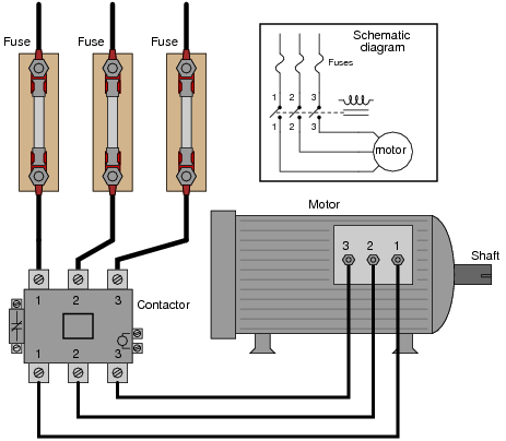
After years of faithful service, one day this motor refuses to start. It makes a “humming” sound when the contactor is energized (relay contacts close), but it does not turn. A mechanic checks it out and determines that the shaft is not seized, but is free to turn. The problem must be electrical in nature!
You are called to investigate. Using a clamp-on ammeter, you measure the current through each of the lines (immediately after each fuse) as another start is once again attempted. You then record the three current measurements:
Line Current
1 52.7 amps
2 51.9 amps
3 0 amps
Determine at least two possible faults which could account for the motor’s refusal to start and the three current measurements taken. Then, decide what your next measurement(s) will be to isolate the exact location and nature of the fault.Reveal answerHere are some possibilities:
- • Fuse #3 blown open
- • Third relay contact damaged (failed open) inside the contactor
- • One winding failed open inside the motor (assuming a “Y” winding configuration)
There are several valid “next steps” you could take from this point. Discuss alternatives with your classmates.
Notes:This is a practical scenario which you and your students should have some fun exploring. If they have never heard of a “contactor” before, this question is a good opportunity to introduce the component. Bring one with you to discussion if you have the opportunity!







Hello, sir.
Please share the name of the Source material/ Text book used in this Article. I will be very thankful to you.
Thanks for doing such a great job.
Good day.
Please I’m Benjamin Akrofi and I need answers to question 8
The name of the site I saw the question is ALL ABOUT CIRCUITS