Facebook
 Google
 GitHub
 Linkedin
AC Electric Circuits
AC phase
24 questions By Tony R. Kuphaldt
-
Question 4 of 24
Using a computer or graphing calculator, plot the sum of these two sine waves:
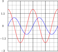
Hint: you will need to enter equations into your plotting device that look something like this:
y1 = sin x
y2 = 2 * sin (x 90)
y3 = y1 y2
Note: the second equation assumes your calculator has been set up to calculate trigonometric functions in angle units of degrees rather than radians. If you wish to plot these same waveforms (with the same phase shift shown) using radians as the unit of angle measurement, you must enter the second equation as follows:
y2 = 2 * sin (x 1.5708)
Reveal answer
Follow-up question: note that the sum of the 1-volt wave and the 2-volt wave does not equate to a 3-volt wave! Explain why.
Notes:Graphing calculators are excellent tools to use for learning experiences such as this. In far less time than it would take to plot a third sine wave by hand, students may see the sinusoidal sum for themselves.
The point of this question is to get students thinking about how it is possible for sinusoidal voltages to not add up as one might expect. This is very important, because it indicates simple arithmetic processes like addition will not be as simple in AC circuits as it was in DC circuits, due to phase shift. Be sure to emphasize this point to your students.
-
Question 5 of 24
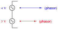
Special types of vectors called phasors are often used to depict the magnitude and phase-shifts of sinusoidal AC voltages and currents. Suppose that the following phasors represent the series summation of two AC voltages, one with a magnitude of 3 volts and the other with a magnitude of 4 volts:
Explain what each of the following phasor diagrams represents, in electrical terms:
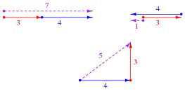
Also explain the significance of these sums: that we may obtain three different values of total voltage (7 volts, 1 volt, or 5 volts) from the same series-connected AC voltages. What does this mean for us as we prepare to analyze AC circuits using the rules we learned for DC circuits?
Reveal answerEach of the phasor diagrams represents two AC voltages being added together. The dotted phasor represents the sum of the 3-volt and 4-volt signals, for different conditions of phase shift between them.
Please note that these three possibilities are not exhaustive! There are a multitude of other possible total voltages that the series-connected 3 volt and 4 volt sources may create.
Follow-up question: in DC circuits, it is permissible to connect multiple voltage sources in parallel, so long as the voltages (magnitudes) and polarities are the same. Is this also true for AC? Why or why not?
Notes:Be sure to discuss with your students that these three conditions shown are not the only conditions possible! I simply chose 0o, 180o, and 90o because they all resulted in round sums for the given quantities.
The follow-up question previews an important subject concerning AC phase: the necessary synchronization or paralleled AC voltage sources.
-
Question 6 of 24
When drawing phasor diagrams, there is a standardized orientation for all angles used to ensure consistency between diagrams. This orientation is usually referenced to a set of perpendicular lines, like the x and y axes commonly seen when graphing algebraic functions:

The intersection of the two axes is called the origin, and straight horizontal to the right is the definition of zero degrees (0o). Thus, a phasor with a magnitude of 6 and an angle of 0o would look like this on the diagram:
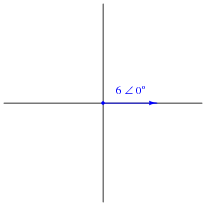
Draw a phasor with a magnitude of 10 and an angle of 100 degrees on the above diagram, as well as a phasor with a magnitude of 2 and an angle of -45 degrees. Label what directions 90o, 180o, and 270o would indicate on the same diagram.
Reveal answer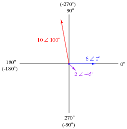
Notes:Graph paper, a ruler, and a protractor may be helpful for your students as they begin to draw and interpret phasor diagrams. Even if they have no prior knowledge of trigonometry or phasors, they should still be able to graphically represent simple phasor systems and even solve for resultant phasors.