
 Facebook
 Google
 GitHub
 Linkedin
AC Electric Circuits
Basic Oscilloscope Operation
25 questions By Tony R. Kuphaldt
-
Question 10 of 25
Assuming the vertical sensitivity control is set to 2 volts per division, and the timebase control is set to 10 μs per division, calculate the amplitude of this “sawtooth” wave (in volts peak and volts peak-to-peak) as well as its frequency.
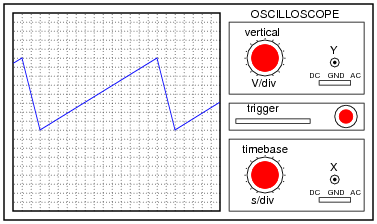
Reveal answer- Epeak = 8 V
- Epeak−to−peak = 16 V
- f = 6.67 kHz
Notes:This question is not only good for introducing basic oscilloscope principles, but it is also excellent for review of AC waveform measurements.
-
Question 11 of 25
Most oscilloscopes can only directly measure voltage, not current. One way to measure AC current with an oscilloscope is to measure the voltage dropped across a shunt resistor. Since the voltage dropped across a resistor is proportional to the current through that resistor, whatever wave-shape the current is will be translated into a voltage drop with the exact same wave-shape.
However, one must be very careful when connecting an oscilloscope to any part of a grounded system, as many electric power systems are. Note what happens here when a technician attempts to connect the oscilloscope across a shunt resistor located on the “hot” side of a grounded 120 VAC motor circuit:
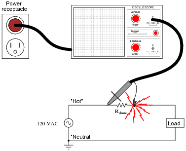
Here, the reference lead of the oscilloscope (the small alligator clip, not the sharp-tipped probe) creates a short-circuit in the power system. Explain why this happens.
Reveal answerThe “ground” clip on an oscilloscope probe is electrically common with the metal chassis of the oscilloscope, which in turn is connected to earth ground by the three-prong (grounded) power plug.
Notes:This is a very important lesson for students to learn about line-powered oscilloscopes. If necessary, discuss the wiring of the power system, drawing a schematic showing the complete short-circuit fault current path, from AC voltage source to “hot” lead to ground clip to chassis to ground prong to ground wire to neutral wire to AC voltage source.
-
Question 12 of 25
Most oscilloscopes have at least two vertical inputs, used to display more than one waveform simultaneously:
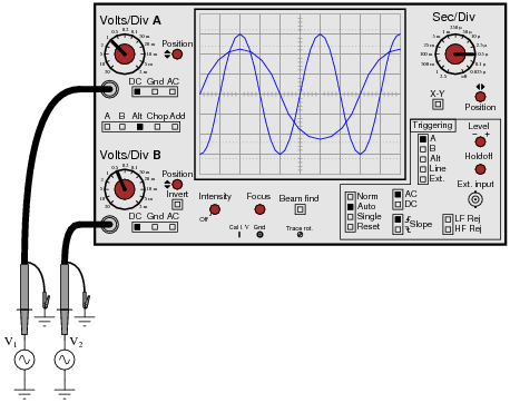
While this feature is extremely useful, one must be careful in connecting two sources of AC voltage to an oscilloscope. Since the “reference” or “ground” clips of each probe are electrically common with the oscilloscope’s metal chassis, they are electrically common with each other as well.
Explain what sort of problem would be caused by connecting a dual-trace oscilloscope to a circuit in the following manner:
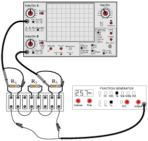
Reveal answerThe oscilloscope will create an earth-grounded short circuit in this series resistor circuit:
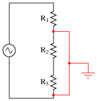
If the signal generator is earth-grounded through its power cord as well, the problem could even be worse:
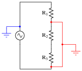
Follow-up question: explain why the second scenario is potentially more hazardous than the first.
Notes:Failing to consider that the “ground” leads on all probes are common to each other (as well as common to the safety ground conductor of the line power system) is a very common mistake among students first learning how to use oscilloscopes. Hopefully, discussing scenarios such as this will help students avoid this problem in their labwork.
Note to Socratic Electronics developers: the oscilloscope shown in figure 01821x01.eps is made up of individual lines, circles, text elements, etc., rather than a single object as is contained in the Xcircuit library file (scope.lps). If you wish to edit the features of this scope, start with the 01821x01.eps image file rather than the library object! Then you may save your modified oscilloscope as a complete object in your own image library for future use.





this is so helpful thank you
Veľká vďaka za poučný článok. Ešte keby tam bolo napísané, ako sa vypočítala tá frekvencia 400 Hz, 40 Hz, 6,67 kHz