
 Facebook
 Google
 GitHub
 Linkedin
AC Electric Circuits
Basic Oscilloscope Operation
25 questions By Tony R. Kuphaldt
-
Question 16 of 25
Shunt resistors are low-value, precision resistors used as current-measuring elements in high-current circuits. The idea is to measure the voltage dropped across this precision resistance and use Ohm’s Law (I = V/R) to infer the amount of current in the circuit:

Since the schematic shows a shunt resistor being used to measure current in an AC circuit, it would be equally appropriate to use an oscilloscope instead of a voltmeter to measure the voltage drop produced by the shunt. However, we must be careful in connecting the oscilloscope to the shunt because of the inherent ground reference of the oscilloscope’s metal case and probe assembly.
Explain why connecting an oscilloscope to the shunt as shown in this second diagram would be a bad idea:
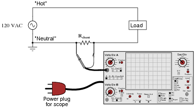
Reveal answerThis would be a bad idea because the oscilloscope’s ground clip would attempt to bypass current around the shunt resistor, through the oscilloscope’s safety ground wire, and back to the grounded terminal of the AC source. Not only would this induce measurement errors, but it could damage the oscilloscope as well.
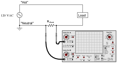
Follow-up question: identify a better way of connecting this oscilloscope to the shunt resistor.
Notes:The ground-referenced clip on an oscilloscope probe is a constant source of potential trouble for those who do not fully understand it! Even in scenarios where there is little or no potential for equipment damage, placing an earth ground reference on a circuit via the probe clip can make for very strange circuit behavior and erroneous measurements. Problems like this frequently occur when new students attempt to connect their oscilloscopes to circuits powered by signal generators whose outputs are also earth-ground referenced.
In response to the follow-up question, the most obvious answer is to reverse the probe connections: ground clip on the left-hand terminal and probe tip on the right-hand terminal. However, even this might not be the best idea, since it creates a “ground loop” between the oscilloscope and the ground connection at the AC source:
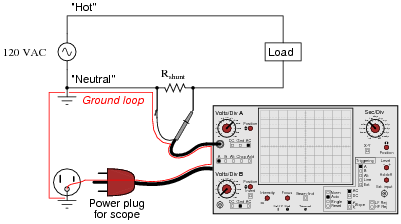
Ground loops are to be avoided in measurement circuits because they may be the source of some very strange effects, including the coupling of noise voltage from entirely unrelated circuits to the one being measured. To avoid this problem, the best solution for measuring the voltage dropped across the shunt resistor is to use two scope probes and set the scope up for differential voltage measurement:
-
Question 17 of 25
An oscilloscope is connected to a battery of unknown voltage. The result is a straight line on the display:
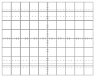
Assuming the oscilloscope display has been properly “zeroed” and the vertical sensitivity is set to 2 volts per division, determine the voltage of the battery.
Reveal answerThe battery voltage is approximately 5.4 volts, connected backward (positive to ground lead, negative to probe tip).
Notes:Measuring voltage on an oscilloscope display is very similar to measuring voltage on an analog voltmeter. The mathematical relationship between scale divisions and range is much the same. This is one reason I encourage students to use analog multimeters occasionally in their labwork, if for no other reason than to preview the principles of oscilloscope scale interpretation.
-
Question 18 of 25
One of the more complicated controls to master on an oscilloscope, but also one of the most useful, is the triggering control. Without proper “triggering,” a waveform will scroll horizontally across the screen rather than staying “locked” in place.
Describe how the triggering control is able to “lock” an AC waveform on the screen so that it appears stable to the human eye. What, exactly, is the triggering function doing that makes an AC waveform appear to stand still?
Reveal answerThe triggering circuit inside the oscilloscope delays the initiation of a beam “sweep” across the screen until the instantaneous voltage value of the waveform has reached the same point, every time, on the wave-shape.
Notes:For students who have every used a “strobe” or “timing” light to make a rotating object appear to “freeze” in place, the concept of oscilloscope triggering makes perfect sense. In fact, a strobe light and a rotating object such as a fan work very well to illustrate the concept of having to “flash” at just the right times in order to make something moving appear to be still.
An interesting comparison to make is between a strobe light (freezing the motion of a fan) set to a frequency that is slightly “off” sync - thereby causing the rotating object to appear to move very slowly - and an oscilloscope with the triggering turned off, and the horizontal sweep speed set in the same manner, adjusted to make the AC waveform horizontally scroll across the screen.
Once your students have seen this comparison, ask them to describe what would be necessary to “trigger” a strobe light so that the moving object always appears to stand still, and cannot “scroll” due to a mismatch in frequencies.






this is so helpful thank you
Veľká vďaka za poučný článok. Ešte keby tam bolo napísané, ako sa vypočítala tá frekvencia 400 Hz, 40 Hz, 6,67 kHz