
 Facebook
 Google
 GitHub
 Linkedin
AC Electric Circuits
Basic Oscilloscope Operation
25 questions By Tony R. Kuphaldt
-
Question 22 of 25
A student just learning to use oscilloscopes connects one directly to the output of a signal generator, with these results:
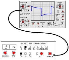
As you can see, the function generator is configured to output a square wave, but the oscilloscope does not register a square wave. Perplexed, the student takes the function generator to a different oscilloscope. At the second oscilloscope, the student sees a proper square wave on the screen:
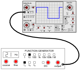
It is then that the student realizes the first oscilloscope has its “coupling” control set to AC, while the second oscilloscope was set to DC. Now the student is really confused! The signal is obviously AC, as it oscillates above and below the centerline of the screen, but yet the “DC” setting appears to give the most accurate results: a true-to-form square wave.
How would you explain what is happening to this student, and also describe the appropriate uses of the ÄC” and “DC” coupling settings so he or she knows better how to use it in the future?
Reveal answer“DC” does not imply that the oscilloscope can only show DC signals and not AC signals, as many beginning students think. Rather, the “DC” setting is the one that should be first used to measure all signals, with the ÄC” setting engaged only as needed.
Notes:The answer I give here is correct, but does not address why the coupling control does what it does, nor does it describe why the square wave signal appears all distorted on the first oscilloscope’s screen. I leave this for your students to research and for you and your students to discuss together in class.
-
Question 23 of 25
There are times when you need to use an oscilloscope to measure a differential voltage that also has a significant common-mode voltage: an application where you cannot connect the oscilloscope’s ground lead to either point of contact. One application is measuring the voltage pulses on an RS-485 digital communications network, where neither conductor in the two-wire cable is at ground potential, and where connecting either wire to ground (via the oscilloscope’s ground clip) may cause problems:
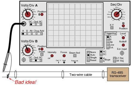
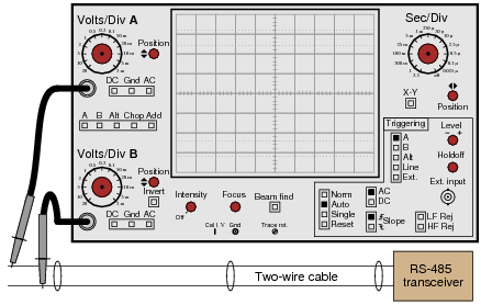
One solution to this problem is to use both probes of a dual-trace oscilloscope, and set it up for differential measurement. In this mode, only one waveform will be shown on the screen, even though two probes are being used. No ground clips need be connected to the circuit under test, and the waveform shown will be indicative of the voltage between the two probe tips.
Describe how a typical oscilloscope may be set up to perform differential voltage measurement. Be sure to include descriptions of all knob and button settings (with reference to the oscilloscope shown in this question):
Reveal answer
- Both channels must be set to same vertical sensitivity (volts/division)
- Both channels should be set for same vertical coupling (both DC or both AC)
- Channel selection must be set to “Add”
- One channel must be inverted (this turns the “addition” into “subtraction”)
Notes:This question is best followed by a demonstration or a lab exercise where students get to see firsthand how it works.
-
Question 24 of 25
A very common accessory for oscilloscopes is a ×10 probe, which effectively acts as a 10:1 voltage divider for any measured signals. Thus, an oscilloscope showing a waveform with a peak-to-peak amplitude of 4 divisions, with a vertical sensitivity setting of 1 volt per division, using a ×10 probe, would actually be measuring a signal of 40 volts peak-peak:
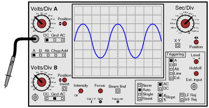
Obviously, one use for a ×10 probe is measuring voltages beyond the normal range of an oscilloscope. However, there is another application that is less obvious, and it regards the input impedance of the oscilloscope. A ×10 probe gives the oscilloscope 10 times more input impedance (as seen from the probe tip to ground). Typically this means an input impedance of 10 MΩ (with the ×10 probe) rather than 1 MΩ (with a normal 1:1 probe). Identify an application where this feature could be useful.
Reveal answerI won’t give away an answer here, but I will provide a hint in the form of another question: why is it generally a good thing for voltmeters to have high input impedance? Or conversely, what bad things might happen if you tried to use a low-impedance voltmeter to measure voltages?
Notes:Increased input impedance is often a more common reason for choosing ×10 probes, as opposed to increased voltage measurement range. The answer to this question is more readily grasped by students after they have worked with loading-sensitive electronic circuits.





this is so helpful thank you
Veľká vďaka za poučný článok. Ešte keby tam bolo napísané, ako sa vypočítala tá frekvencia 400 Hz, 40 Hz, 6,67 kHz