
 Facebook
 Google
 GitHub
 Linkedin
Discrete Semiconductor Devices and Circuits
Bipolar Junction Transistor (BJT) theory
28 questions By Tony R. Kuphaldt
-
Question 22 of 28
Draw the polarities ( and -) of the applied voltages necessary to turn both these transistors on:

Also, draw the direction of the controlled current (flowing between collector and emitter) that will result from a power source properly connected between these terminals.
Reveal answer
Follow-up question: draw the voltage sources necessary for generating the “controlled” current traced in these diagrams, so that the applied voltage polarity between collector and emitter is evident.
Notes:This is a very important concept for students to grasp: how to turn a BJT on with an applied voltage between base and emitter, and also which direction the controlled current goes through it. Be sure to spend time discussing this, for it is fundamental to their understanding of BJT operation.
-
Question 23 of 28
Students new to the study of transistors often have difficulty remembering the proper directions of currents through bipolar junction transistors, since there are three different currents (IB, IC, IE) and they must “mesh” through the transistor in a particular way.
Draw the proper current directions for each of these transistors, and explain how you are able to remember the correct directions they go:

Reveal answer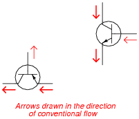
Notes:Rather than present a “rule of thumb” to use in remembering the proper current directions, I opt to let the students figure this out on their own. An important element of this should be the mathematics of BJT currents, primarily this equation:
$$I_E=I_C+I_B$$
This relationship, combined with Kirchhoff’s Current Law, should provide all the help necessary to formulate a rule.
-
Question 24 of 28
Predict how all three transistor currents (IB, IC, and IE) will be affected as a result of the following faults. Consider each fault independently (i.e. one at a time, no multiple faults):

- Base resistor RB fails open:
- Collector resistor RC fails open:
- Solder bridge (short) past base resistor RB:
- Solder bridge (short) past collector resistor RC:
For each of these conditions, explain why the resulting effects will occur.
Reveal answer- Base resistor RB fails open: All three currents stop.
- Collector resistor RC fails open: Base current unchanged, collector current stops, emitter current decreases to value of base current (IE = IB).
- Solder bridge (short) past base resistor RB: All three currents greatly increase, transistor will likely overheat and fail.
- Solder bridge (short) past collector resistor RC: Base current unchanged, collector current increases slightly (ideally will not change at all!), transistor dissipates more power in the form of heat (may overheat).:
Notes:The purpose of this question is to approach the domain of circuit troubleshooting from a perspective of knowing what the fault is, rather than only knowing what the symptoms are. Although this is not necessarily a realistic perspective, it helps students build the foundational knowledge necessary to diagnose a faulted circuit from empirical data. Questions such as this should be followed (eventually) by other questions asking students to identify likely faults based on measurements.





What surprises me is the following: I did not see any mentioning of the most important BJT parameter: Transconductance gm.
(Instead, you are stating that the beta-value would be a very important parameter - which is NOT the case!).
Like some other low-level electronic books and papers you treat the BJT as a cittent-controlled device - this is simply wrong.
There is not a single proof that the BJT would be a CCCS !
However, there are many theoretical explanations, measurements and observable facts which clearly show that the BJT is - of course - voltage-controlled. Who can deny it ? With which arguments? Ic=beta x Ib is just a formula - a misinterpretation of Ib=Ic/beta.