Facebook
 Google
 GitHub
 Linkedin
Discrete Semiconductor Devices and Circuits
Class A BJT Amplifiers
62 questions By Tony R. Kuphaldt
-
Question 43 of 62
Sometimes you will see amplifier circuits expressed as collections of impedances and dependent sources:
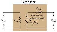
With this model, the amplifier appears as a load (Zin) to whatever signal source its input is connected to, boosts that input voltage by the gain factor (AV), then outputs the boosted signal through a series output impedance (Zout) to whatever load is connected to the output terminals:
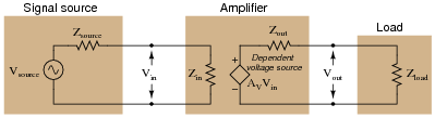
Explain why all these impedances (shown as resistors) are significant to us as we seek to apply amplifier circuits to practical applications. Which of these impedances do you suppose are typically easier for us to change, if they require changing at all?
Reveal answerZin should equal Zsource and Zload should equal Zout for maximum power transfer from source to load. Typically, the values of Zsource and Zload are fixed by the nature of the source and load devices, respectively, and the only impedances we have the freedom to alter are those within the amplifier.
Notes:This question has multiple purposes: to introduce students to the modeling concept of a dependent source, to show how an amplifier circuit may be modeled using such a dependent source, and to probe into the importance of impedances in a complete amplification system: source, amplifier, and load. Many interesting things to discuss here!
-
Question 44 of 62
Complete the table of output voltages, output currents, and input currents for several given values of input voltage in this common-collector amplifier circuit. Assume that the transistor is a standard silicon NPN unit, with a nominal base-emitter junction forward voltage of 0.7 volts:

Vin Vout Iin Iout 0.8 V 1.5 V 3.0 V 4.5 V 6.0 V 7.5 V
Calculate the amount of impedance “seen” by the input voltage source Vin, given the following definition for impedance:$$Z_{in}=\frac{\triangle V_{in}}{\triangle I_{in}}=$$
Reveal answerVin Vout Iin Iout 0.8 V 0.1 V 2.80 μA 0.213 mA 1.5 V 0.8 V 22.4 μA 1.70 mA 3.0 V 2.3 V 64.4 μA 4.89 mA 4.5 V 3.8 V 106 μA 8.09 mA 6.0 V 5.3 V 148 μA 11.3 mA 7.5 V 6.8 V 190 μA 14.5 mA $$Z_{in}=\frac{\triangle V_{in}}{\triangle I_{in}}=35.72kΩ$$
Notes:The purpose of this question, besides providing practice for common-collector circuit DC analysis, is to show the current-amplification properties of the common-collector amplifier. This is an important feature, as there is no voltage amplification in this type of amplifier circuit.
This approach to determining transistor amplifier circuit impedance is one that does not require prior knowledge of amplifier configurations. In order to obtain the necessary data to calculate voltage gain, all one needs to know are the “first principles” of Ohm’s Law, Kirchhoff’s Laws, and basic operating principles of a bipolar junction transistor. This question is really just a thought experiment: exploring an unknown form of circuit by applying known rules of circuit components. If students doubt the efficacy of “thought experiments,” one need only to reflect on the success of Albert Einstein, whose thought experiments as a patent clerk (without the aid of experimental equipment) allowed him to formulate the basis of his Theories of Relativity.
-
Question 45 of 62
Calculate the approximate input impedance (Zin) of this amplifier circuit:

Also, explain why input impedance is an important factor in amplifier circuits.
Reveal answerZin = 152 kΩ
I won’t directly tell you why input impedance is an important factor for amplifier circuits, but I’ll give you a hint: Maximum Power Transfer Theorem.
Notes:Ask you students to compare the input impedance of this amplifier with the load impedance. Does the transistor “match” impedances like a transformer does? Ask them to explain both the similarities and the differences between transformers and transistors as impedance-matching devices.