Facebook
 Google
 GitHub
 Linkedin
Discrete Semiconductor Devices and Circuits
Class A BJT Amplifiers
62 questions By Tony R. Kuphaldt
-
Question 37 of 62
Amplifier distortion occurs when its gain varies as a function of the instantaneous signal amplitude. That is, some parts of the signal waveform become amplified more than others, and this results in the waveform taking on a slightly different shape.
All active devices, bipolar junction transistors included, are nonlinear to some extent. This term means that their gain varies throughout their operating ranges. During the 1920’s, an electrical engineer named Harold Black was pondering this problem in the design of telephone system amplifiers. His solution came to him in a flash of insight one day, as he was commuting from work on a ferry boat. Explain what his solution to this problem was.
Reveal answerHarold Black is credited as the first to apply negative feedback as a solution to the problem of nonlinearity in electronic amplifiers.
Challenge question: since negative feedback has the undesirable effect of diminishing overall amplifier gain, it would seem at first that low distortion and high gain are mutually exclusive design goals for an amplifier. Is this true, or is there a way to obtain both low distortion and high gain from an amplifier? If so, how?
Notes:Although Black’s solution has been wildly successful in amplifier design, it also finds application in a wide range of processes. Control theory, for example, where machines are automated in such a way as to stabilize physical variables such as pressure, flow, temperature, etc., depends heavily on negative feedback as an operating principle.
An interesting historical side-note is that Black’s 1928 patent application was initially rejected on the grounds that he was trying to submit a perpetual motion device! The concept of negative feedback in an amplifier circuit was so contrary to established engineering thought at the time, that Black experienced significant resistance to the idea within the engineering community. At that time the United States patent office was inundated with fraudulent “perpetual motion” claims, and so dismissed Black’s invention at first sight.
-
Question 38 of 62
A popular method of “reclaiming” some of the lost voltage gain resulting from the addition of an emitter resistor (RE) to a common-emitter amplifier circuit is to connect a “bypass” capacitor in parallel with that resistor:
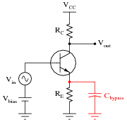
Explain why this technique works to increase the circuit’s AC voltage gain, without leading to the problems associated with directly grounding the emitter.
Reveal answerTo an AC signal, a large capacitor “looks” like a lower impedance than the emitter resistor. Usually, this capacitor is sized such that XC is very small.
The addition of a bypass capacitor maintains DC stability, because DC cannot go through the capacitor but must go through the emitter resistor (RE) just as if the bypass capacitor were not there at all.
Notes:This question provides a good opportunity to review capacitive reactance (XC). The polarized capacitor symbol hints at the capacitor’s relatively large value, and your students should realize that a large capacitor’s reactance will be relatively low to most AC signals. An idea to help communicate the “bypass” concept is to have one of your students re-draw the circuit as “seen” from the perspective of an AC signal, not a DC signal. With the capacitor effectively acting as a short-circuit to AC signals, what does the amplifier circuit look like to those signals?
-
Question 39 of 62
Some common-emitter amplifier circuits use partial bypassing of emitter resistance, with the bypass capacitor connected in parallel with only one of two series resistors:

Explain the purpose of this arrangement. How does this differ in performance from the simple one-resistor emitter feedback design, or a grounded-emitter amplifier with no emitter resistor at all?
Reveal answerThis design is a compromise between full bypassing and no emitter resistor at all. It provides all the DC voltage gain and Q-point stability of full bypassing, while providing more AC voltage gain stability than full bypassing.
Notes:After reviewing the simple (no-resistor) common-emitter circuit design, and the full-bypass design, it should be apparent to students that this circuit is a hybrid of the two previous designs. Likewise, it should come as little surprise that its performance characteristics lie somewhere between the two previous designs.