
 Facebook
 Google
 GitHub
 Linkedin
Discrete Semiconductor Devices and Circuits
Class A BJT Amplifiers
62 questions By Tony R. Kuphaldt
-
Question 16 of 62
Choose values for the collector and emitter resistors that will yield a voltage gain of approximately 5 for the following common-emitter amplifier circuit:

- RC =
- RE =
Reveal answerThe following resistor values are but one solution for this problem. There is actually an infinite number of correct resistor value pairs that will yield the requested voltage gain!
- RC = 10 kΩ
- RE = 2 kΩ
Notes:You might want to ask your students what practical maximum and minimum resistor values they would choose between when designing such an amplifier circuit. What would be the danger of selecting resistors too low in value? What would be wrong with choosing resistors too high in value? They might not be ready to answer these questions (especially the latter) until after having studied amplifier impedance calculations, though!
-
Question 17 of 62
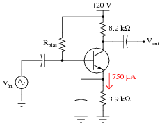
Calculate the approximate voltage gain (AV) for the following bypassed common-emitter amplifier circuit, assuming a quiescent (DC) emitter current value of 750 μA. Also calculate the quiescent DC voltage measured at the transistor’s collector terminal with respect to ground (VC). Assume a silicon transistor:
- AV ≈
- VC ≈
Reveal answer- AV ≈ 246
- VC ≈ 13.85 volts
Notes:Nothing much to comment on here - just some practice on common-emitter amplifier calculations. Note that the approximations given here are based on the following assumptions:
- 0.7 volts drop (exactly) across base-emitter junction.
- Infinite DC current gain (β) for transistor (IB = 0 μA ; IC = IE).
- Negligible loading of bias voltage divider by the emitter resistance.
- Negligible dynamic emitter resistance (r′e = 0 Ω )
This question lends itself well to group discussions on component failure scenarios. After discussing how to calculate the requested values, you might want to ask students to consider how these values would change given some specific component failures (open resistors, primarily, since this is perhaps the most common way that a resistor could fail).
-
Question 18 of 62
Calculate the approximate voltage gain (AV) for the following common-emitter amplifier circuit, expressing it both as a ratio and as a figure in decibels. Also calculate the quiescent DC voltages measured at the three terminals of the transistor with respect to ground (VB, VE, and VC). Assume a silicon transistor:

- AV (as a ratio) ≈
- AV (in decibels) ≈
- VB ≈
- VE ≈
- VC ≈
Reveal answer- AV (as a ratio) ≈ 8.148
- AV (in decibels) ≈ 18.22 dB
- VB ≈ -1.355 volts
- VE ≈ -0.655 volts
- VC ≈ -6.664 volts
Notes:Nothing much to comment on here - just some practice on common-emitter amplifier calculations. Note that the approximations given here are based on the following assumptions:
- 0.7 volts drop (exactly) across base-emitter junction.
- Infinite DC current gain (β) for transistor (IB = 0 μA ; IC = IE).
- Negligible loading of bias voltage divider by the emitter resistance.
- Negligible dynamic emitter resistance (r′e = 0 Ω )
This question lends itself well to group discussions on component failure scenarios. After discussing how to calculate the requested values, you might want to ask students to consider how these values would change given some specific component failures (open resistors, primarily, since this is perhaps the most common way that a resistor could fail).


