Facebook
 Google
 GitHub
 Linkedin
Digital Circuits
Electromechanical Relay Logic
19 questions By Tony R. Kuphaldt
-
Question 7 of 19
The following schematic is of a relay circuit that emulates a standard digital logic gate function:
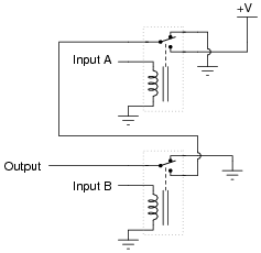
Write a truth table for this circuit’s function, and determine what name best represents it (AND, OR, NAND, NOR, or NOT).
Reveal answerThis is an AND function.
Notes:Ask your students to identify what arrangement the relay contacts are connected it: series or parallel? Does this contact arrangement make sense with regard to the established function of the gate?
-
Question 8 of 19
The following schematic is of a relay circuit that emulates a standard digital logic gate function:
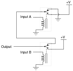
Write a truth table for this circuit’s function, and determine what name best represents it (AND, OR, NAND, NOR, or NOT).
Reveal answerThis is an OR function.
Notes:Ask your students to identify what arrangement the relay contacts are connected it: series or parallel? Does this contact arrangement make sense with regard to the established function of the gate?
-
Question 9 of 19
A type of electrical diagram convention optimal for representing electromechanical relay circuits is the ladder logic diagram. An example of a “ladder logic” diagram is shown here:

Each parallel circuit branch is represented as its own horizontal “rung” between the two vertical “rails” of the ladder. As you may have noticed, some of the symbols resemble standard electrical/electronic schematic symbols (toggle switches, for instance), while others are unique to ladder logic diagrams (heater elements, solenoid coils, lamps).
Where do the circuits shown obtain their electrical power? What do “L1” and “L2” represent? How are relay coils and contacts represented in a ladder logic diagram? Answer each of these questions by expanding upon the diagram shown above: draw the components necessary to show a complete electrical circuit (i.e. details of the power source), as well as an additional rung (or two) showing a relay coil actuated by some sort of switch contact, and the relay contact controlling power to a second indicator lamp.
Reveal answerThis is just one example of how the ladder logic diagram could be expanded:

“L1” and “L2” represent the “hot” and “neutral” lines, respectively, in a 120 volt AC power system. Often, the control circuit power is obtained from a step-down transformer, which is in turn fed by a higher voltage source (usually one phase of a 480 volt AC three-phase system, in American industrial applications).
Notes:If students don’t raise this point on their own, direct their attention to the relay coil and contact symbols. What looks strange here? What sort of electrical component are students familiar associating with the “CR1” contact symbol? Does it make sense to use this symbol to symbolize a normally-open switch (relay) contact? If we wished to show a normally-closed relay contact instead, how would we modify the diagram?