Facebook
 Google
 GitHub
 Linkedin
Digital Circuits
Electromechanical Relay Logic
19 questions By Tony R. Kuphaldt
-
Question 10 of 19
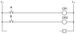
Complete the following ladder logic diagram so that an OR gate function is formed: the indicator lamp energizes if either switch A or switch B is actuated.
Reveal answer
Notes:Discuss with students the fact that relay coils and contacts need not be located near each other in ladder diagrams. While this may be confusing at times, it is a very flexible feature of ladder logic notation, because it gives the author the freedom to locate relay contacts where it makes the most visual sense in the “output” rung of the diagram, without having to coordinate locations of coil and contact as is generally necessary in traditional schematic diagrams. Instead, relay contacts are associated with their respective coils by label, not by proximity on the diagram.
-
Question 11 of 19
In ladder logic diagrams, a normally-open relay contact is drawn as a set of parallel lines, almost like a non-polarized capacitor in an electronic schematic diagram. Normally-closed relay contacts differ in symbolism by having a diagonal line drawn through them.
Analyze the following relay logic circuit, completing the truth table accordingly:

Reveal answer
Notes:Many students find the “line-through-the-contact” a very intuitive way to represent normally-closed relay contacts. Be sure to emphasize that the diagonal line, as well as the name normally-closed, does not refer to any given state of the contact, but rather to the contact’s resting state when the relay coil is de-energized. I have seen teachers put a diagonal line through a relay contact symbol on a ladder logic diagram to indicate the state of the contact being closed by energization of the coil, during the process of explaining how a circuit functioned. This is wrong, as it confuses the concept of contacts being normally-closed with the concept of contacts simply being (energized) closed.
-
Question 12 of 19
The following ladder logic diagram (for a steam heater control) contains a serious mistake:

This is a mistake I’ve seen many students make. Explain what the mistake is, and draw a corrected version of this relay circuit.
Reveal answerNever, ever connect load devices in series in a control circuit such as this!
Notes:Discuss with your students why load devices are never to be connected in series. What would be the effect of doing so? Have them answer this question in terms of normal operation, and also in terms of operation given a failure condition in one of the series-connected load devices.