Facebook
 Google
 GitHub
 Linkedin
Digital Circuits
Electromechanical Relay Logic
19 questions By Tony R. Kuphaldt
-
Question 16 of 19
Safety is a paramount concern in electrical systems. Generally, we try to design electrical circuits so that if and when they fail, they will do so in the manner safest to those people working around them, and to the equipment and process(es) controlled by the circuit.
One of the more common failure modes of circuits having wires strung through metal conduit is the accidental ground, or ground fault, where the electrical insulation surrounding a wire fails, resulting in contact between that wire and a grounded metal surface.
Suppose an accidental ground were to occur at the point shown in this ladder diagram:
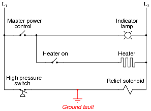
What would be the result of this fault? Hint: you will need to know something about the L1/L2 power source in order to answer this question!
What would be the result if the L1/L2 power connections were reversed?
Reveal answerIn a properly designed system, with L2 grounded at the power source, this fault will result in a blown fuse when the pressure switch closes. In a circuit with L1 and L2 reversed, this same ground fault would energize the relief solenoid, with or without the pressure switch’s “permission.”
Notes:The ultimate purpose of this question is not to ascertain the effects of a particular fault so much as it is to derive a general rule regarding the construction of industrial control circuits. Students should be able to see the benefits of having L2 (the grounded power rail) on the right-hand side of the circuit, but can they induce the general safety principle to be applied in all control circuits? What is “special” about having L2 on the right-hand side of the ladder diagram?
-
Question 17 of 19
Complete the following ladder logic diagram so that an AND gate function is formed: the indicator lamp energizes if and only if both switch A and switch B are simultaneously actuated.

Reveal answer
Notes:Discuss with students the fact that relay coils and contacts need not be located near each other in ladder diagrams. While this may be confusing at times, it is a very flexible feature of ladder logic notation, because it gives the author the freedom to locate relay contacts where it makes the most visual sense in the “output” rung of the diagram, without having to coordinate locations of coil and contact as is generally necessary in traditional schematic diagrams. Instead, relay contacts are associated with their respective coils by label, not by proximity on the diagram.
-
Question 18 of 19
Write a truth table for each of the indicator lamps in the following ladder diagram, and determine which logic function (AND, OR, NAND, NOR, or NOT) best describes each lamp’s behavior with respect to the status of the input switches.

Reveal answer
Each of the lamps exhibits the behavior of a “NOR” gate.
Notes:This question provides a good opportunity for students to practice analyzing relay logic circuits, and it also foreshadows DeMorgan’s Theorem in its dual implementation of the NOR function. Note to your students how more than one contact is being used on control relays CR1 and CR2!