Facebook
 Google
 GitHub
 Linkedin
AC Electric Circuits
Impedance
19 questions By Tony R. Kuphaldt
-
Question 10 of 19
Suppose you were given a component and told it was either a resistor, an inductor, or a capacitor. The component is unmarked, and impossible to visually identify. Explain what steps you would take to electrically identify what type of component it was, and what its value was, without the use of any test equipment except a signal generator, a multimeter (capable of measuring nothing but voltage, current, and resistance), and some miscellaneous passive components (resistors, capacitors, inductors, switches, etc.). Demonstrate your technique if possible.
Reveal answerDid you really think I would give you the answer to this?
Notes:This is an excellent opportunity to brainstorm as a group and experiment on real components. There is obviously more than one way to make the determinations of identity and value! Use the class time to engage your students in lively discussion and debate over how to approach this practical problem.
-
Question 11 of 19
Suppose you were given two components and told one was an inductor while the other was a capacitor. Both components are unmarked, and impossible to visually distinguish or identify. Explain how you could use an ohmmeter to distinguish one from the other, based on each component’s response to direct current (DC).
Then, explain how you could approximately measure the value of each component using nothing more than a sine-wave signal generator and an AC meter capable only of precise AC voltage and current measurements across a wide frequency range (no direct capacitance or inductance measurement capability), and show how the reactance equation for each component (L and C) would be used in your calculations.
Reveal answerDid you really think I would give you the answers to a question like this?
Challenge question: suppose the only test equipment you had available was a 6-volt battery and an old analog volt-milliammeter (with no resistance check function). How could you use this primitive gear to identify which component was the inductor and which was the capacitor?
Notes:This is an excellent opportunity to brainstorm as a group and experiment on real components. The purpose of this question is to make the reactance equations more “real” to students by having them apply the equations to a realistic scenario. The ohmmeter test is based on DC component response, which may be thought of in terms of reactance at a frequency at or near zero. The multimeter/generator test is based on AC response, and will require algebraic manipulation to convert the canonical forms of these equations to versions appropriate for calculating L and C.
-
Question 12 of 19
If a sinusoidal voltage is applied to an impedance with a phase angle of 0o, the resulting voltage and current waveforms will look like this:
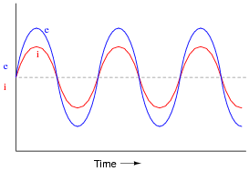
Given that power is the product of voltage and current (p = i e), plot the waveform for power in this circuit.
Reveal answer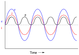
Notes:Ask your students to observe the waveform shown in the answer closely, and determine what sign the power values always are. Note how the voltage and current waveforms alternate between positive and negative, but power does not. Of what significance is this to us? What does this indicate about the nature of a load with an impedance phase angle of 0o?