
 Facebook
 Google
 GitHub
 Linkedin
Discrete Semiconductor Devices and Circuits
Multi-Stage Transistor Amplifiers
15 questions By Tony R. Kuphaldt
-
Question 4 of 15
In some applications where transistors must amplify very high currents, bipolar transistors are paralleled together so that their current ratings add:
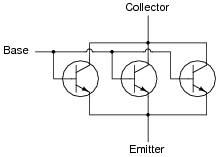
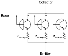
However, if transistors are directly paralleled as shown, reliability problems may develop. A better way of “ganging” multiple transistors together is to connect a low-value swamping resistor to each emitter terminal:

Explain what purpose these resistors serve in a paralleled transistor network. And what exactly does “swamping” mean, anyway?
Reveal answerSwamping is a design term, meaning to introduce a quantity or quantities into a circuit such that any intrinsic differences between components become insignificant in comparison. In this circuit, the swamping resistors help ensure that the total controlled current is more evenly split between the three transistors.
Follow-up question: can you think of any disadvantages to using swamping resistors in high-power circuitry?
Notes:I once had the misfortune of performing component-level repair on a large power inverter (208 volt, three-phase) that used large “banks” of directly paralleled bipolar transistors for the final switching elements. These inverters had a bad habit of destroying transistors, and I noticed that invariably there would be only one or two transistors out of about a dozen on each heat sink rail that were blown - and I mean blown, holes blasted through the metal TO-3 cases! - while the rest were perfectly fine. These transistor banks did not employ swamping resistors, and so the current distribution between them was quite unbalanced.
In case students ask, you should let them know that swamping resistors are not just used in transistor banks. Large rectifier diode banks (where multiple diodes are paralleled) also benefit from swamping resistors.
As for applications where swamping resistors are impractical, it is possible to gain better reliability by using more transistors (or diodes) than necessary with an even current split. In other words, over-build the circuit.
-
Question 5 of 15
In some applications where transistors must amplify very high currents, bipolar transistors are paralleled together so that their current ratings add. When this is done, it is a good idea to use swamping resistors at the transistor emitter connections to help ensure even balancing of currents:
However, if we use MOSFETs instead of BJTs, we do not have to use swamping resistors:
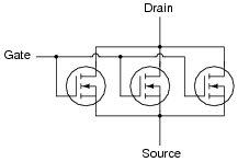
Explain why MOSFETs do not require swamping resistors to help evenly distribute current, while BJTs do.
Reveal answerThe amount of controlling voltage varies with temperature for the BJT, but not for the MOSFET.
Notes:The answer given here is purposefully vague. Let your students do the necessary research! Tell them that manufacturers’ application notes are valuable sources of information for questions such as this.
-
Question 6 of 15
The first amplifier circuit shown here is direct-coupled, while the second is capacitively coupled.
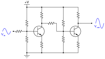
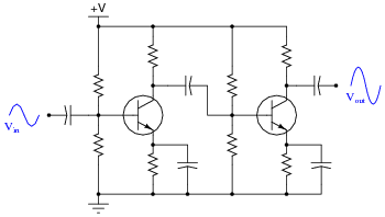
Which of these two designs would be more suitable for use in a DC voltmeter circuit (amplifying a measured DC voltage)? What applications would the other amplifier design be suited for?
Reveal answerThe direct-coupled amplifier circuit’s bandwidth extends down to 0 Hz, unlike the other amplifier. This makes it suitable for DC signal amplification. The capacitive-coupled amplifier circuit would be better suited for applications where AC signals are solely dealt with.
Follow-up question: in each of these amplifier circuits, identify the point at which the signal’s phase becomes shifted by 180o. In other words, show where the voltage signal becomes inverted, and then inverted again, so that the output is in phase with the input.
Notes:A good question to ask your students is, “What is bandwidth?” It is important that your students understand the basic concept of “bandwidth”, and what factors influence it in a circuit.
Ask your students to suggest possible values (in microfarads) for the coupling capacitor in the second circuit, based on common resistor values (between 1 kΩ and 100 kΩ), and a modest audio frequency range (1 kHz to 20 kHz). No exact values are needed here, but it is important that they be able to make an approximate estimation of the necessary (minimum) capacitance, if for no other reason than to demonstrate their comprehension of the coupling capacitor’s intended purpose.





Just Awesome💔💔💔💔
Who wrote this article / worksheet? I really enjoyed it and would like to see more of their stuff