
 Facebook
 Google
 GitHub
 Linkedin
Discrete Semiconductor Devices and Circuits
Multi-Stage Transistor Amplifiers
15 questions By Tony R. Kuphaldt
-
Question 10 of 15
Radio-frequency amplifiers often use small inductors called peaking coils in the coupling circuitry between transistor stages. Describe the purpose of these inductors.
Reveal answerPeaking coils are added to amplifier circuits to help counteract capacitive reactance at high frequencies.
Notes:The answer I gave for this question is very minimal, and is just enough to give your students a hint. Ask your students to explain why capacitive reactance is an issue in high-frequency transistor amplifier circuits, and why an inductor would be used to counter XC. Also, ask if there are any disadvantages to inserting peaking coils into amplifier circuits.
-
Question 11 of 15
One design of push-pull audio amplifier uses two identical transistors and a center-tapped transformer to couple power to the load (usually a speaker, in an audio-frequency system):

Unlike complementary-pair push-pull amplifier circuits, this circuit absolutely requires a preamplifier stage called a phase splitter, comprised here by transistor Q1 and resistors R3 and R4.
Explain what the purpose of the “phase splitter” circuit is, and why it is necessary to properly drive the power transistors Q2 and Q3.
Hint: determine the phase relationships of the voltage signals at the base, collector, and emitter terminals of transistor Q1, with respect to ground.
Reveal answerA “phase splitter” circuit produces two complementary output voltages (180o phase-shifted from each other), as necessary to drive the power transistors at opposite times in the audio waveform cycle.
Follow-up question: typically, the collector and emitter resistors of the phase splitter circuit (R3 and R4 in this example) are equally sized. Explain why.
Notes:Ask your students to qualitatively analyze the voltage signal waveforms at all parts of this circuit. When does Q1 conduct current? When does Q2 conduct current?
Also, discuss the operational class of this amplifier circuit. Is it Class B, or Class AB? What would need to be changed in order to shift the circuit’s operational mode?
Explain to your students that this circuit topology was very common in the days of electron tube electronics, when there was no such thing as complementary active components (i.e., NPN versus PNP). Triode, tetrode, and pentode tubes are all positive-driven devices, conducting more current as the grid voltage becomes more positive. Thus, the only way to make a push-pull amplifier with electron tubes was to use a pair to drive the center-tapped winding of an audio power transformer, and use a phase splitter circuit to drive the two tubes.
Most modern (semiconductor) audio amplifier designs avoid the use of an audio output transformer. Ask your students why they think this may be the case.
-
Question 12 of 15
Examine this push-pull audio amplifier circuit:
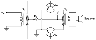
Answer the following questions about this circuit based on your analysis of it:
- How is phase splitting accomplished in this circuit?
- What is the purpose of resistor R1?
- What would happen if resistor R1 failed open?
- What would happen if the wire connecting the base of transistor Q2 to the input transformer (T1) were to fail open?
Reveal answer- The input transformer T1 provides phase splitting.
- R1 establishes the Q point of both transistors.
- If R1 failed open, both transistors would go into cutoff mode.
- If the wire connecting the base of transistor Q2 to the input transformer (T1) were to fail open, one-half of the output waveform would become clipped.
Notes:Ask your students to give detailed reasons for their answers. The answers provided for this question are minimal - it is your job as the instructor to ensure students are thinking their way through this question, and not just repeating something they’ve read or heard from others.




Just Awesome💔💔💔💔
Who wrote this article / worksheet? I really enjoyed it and would like to see more of their stuff