
 Facebook
 Google
 GitHub
 Linkedin
Discrete Semiconductor Devices and Circuits
Multi-Stage Transistor Amplifiers
15 questions By Tony R. Kuphaldt
-
Question 13 of 15
The following amplifier circuit has a problem. Despite the presence of a strong input signal (as verified by an oscilloscope measurement at TP1), there is no sound coming from the speaker:
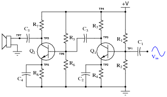
Explain a logical, step-by-step approach to identifying the source of the problem, by taking voltage signal measurements. Remember, the more efficient your troubleshooting technique is (the fewer measurements taken), the better!
Reveal answerI’ll let you have fun determining your own strategies here!
Notes:This question can easily occupy a large portion of your discussion time, so be sure to make room for it in your schedule!
A great way to help students grasp the concepts involved in this circuit as well as improve their troubleshooting technique, is to make a large-scale demonstration board of this circuit, which you can fault on the back side by disconnecting wires, opening or closing switches, etc. Then, have the students take an oscilloscope and practice finding problems in the circuit by voltage measurement only. I have built similar demonstration boards for my own classroom, and have found them to be extremely useful in building and assessing troubleshooting skills.
-
Question 14 of 15
A common wideband transistor amplifier circuit is the cascode design, using common-emitter and common-base transistor stages:

What advantage(s) does the cascode amplifier have over “normal” single- or multi-stage amplifier designs? What, specifically, makes it well suited for high-frequency applications, such as RF (Radio Frequency) signal amplifiers?
Reveal answerThe combination of a common-collector first stage and a common-base second stage significantly reduces the debilitating effects of interjunction capacitance within the two transistors. Most cascode amplifiers require no neutralization, either: a testament to the effectiveness of the design.
Notes:This is one of the few popular applications for the common-base transistor amplifier configuration, and it is a solution that has been implemented with field-effect transistors as well as bipolar transistors (and even electron tubes, before that!). Ask your students to explain how the circuit works, especially noting the voltage gain of each stage, and the locations of interjunction (Miller-effect) capacitances in the circuit.
-
Question 15 of 15
Suppose the following three-stage transistor amplifier were constructed:

With no emitter swamping resistors anywhere in this circuit, the voltage gain of each stage is guaranteed to be large, but unstable as well. With three stages arranged like this, one feeding into the next, the final voltage gain will be very large, and very unstable.
However, if we add another resistor to the circuit (Rfeedback), something very interesting takes place. Suddenly, the amplifier circuit’s overall voltage gain is decreased, but the stability of this gain becomes much improved:
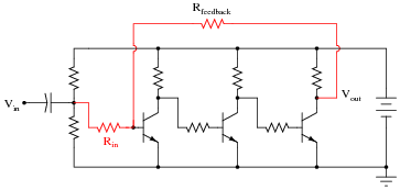
Interestingly, the voltage gain of such a circuit will be nearly equal to the quotient of the two highlighted resistors, \(R_{feedback}\) and \(R_{in}\):
$$A_V \approx \frac{R_{feedback}}{R_{in}}$$
This approximation holds true for large variations in individual transistor gain (β) as well as temperature and other factors which would normally wreak havoc in the circuit with no feedback resistor in place.
Describe what role the feedback resistor plays in this circuit, and explain how the addition of negative feedback is an overall benefit to this circuit’s performance. Also, explain how you can tell this feedback is negative in nature (“degenerative”).
Reveal answerThe feedback resistor provides a signal path for negative feedback, which “tames” the unruly gain and instability otherwise inherent to such a crude three-stage transistor amplifier circuit.
We can tell that the feedback is negative in nature because it comes from an odd number of inverting amplifier stages (there is still an inverse relationship between output and input).
Follow-up question: how much effect do you suppose the replacement of a transistor with a slightly different β or r′e parameter would affect each circuit?
Notes:Although the circuit shown is a little too crude to be practical, it does illustrate the power of negative feedback as a stabilizing influence.
The question regarding the de-generative nature of the feedback is an important one. Discuss with your students how one could not simply pick up the feedback signal from anywhere in the circuit!




Just Awesome💔💔💔💔
Who wrote this article / worksheet? I really enjoyed it and would like to see more of their stuff