Facebook
 Google
 GitHub
 Linkedin
Discrete Semiconductor Devices and Circuits
Signal Modulation
31 questions By Tony R. Kuphaldt
-
Question 16 of 31
A resistive DC load receives pulse-width modulated (PWM) power from a controller circuit, and an oscilloscope shows the load voltage waveform as such:
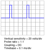
Calculate the duty cycle of this waveform, and also the average power dissipated by the load assuming a load resistance of 1.8 Ω.
Reveal answerDuty cycle ≈ 12.5%
Paverage ≈ 250 W
Follow-up question: which oscilloscope setup parameters (vertical sensitivity, probe ratio, coupling, and timebase) are necessary for performing these calculations? Which parameters are unnecessary, and why?
Notes:Calculating the duty cycle should be easy. Calculating load power dissipation requires some thought. If your students do not know how to calculate average power, suggest this thought experiment: calculating power dissipation at 0% duty cycle, at 100% duty cycle, and at 50% duty cycle. The relationship between duty cycle and average power dissipation is rather intuitive if one considers these conditions.
If a more rigorous approach is required to satisfy student queries, you may wish to pose another thought experiment: calculate the energy (in units of Joules) delivered to the load for a 50% duty cycle, recalling that Watts equals Joules per second. Average power, then, is calculated by dividing Joules by seconds over a period of one or more whole waveform cycles. From this, the linear relationship between duty cycle and average power dissipation should be clear.
-
Question 17 of 31
A resistive DC load receives pulse-width modulated (PWM) power from a controller circuit, and an oscilloscope shows the load voltage waveform as such:
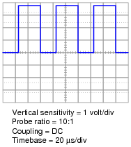
Calculate the duty cycle of this waveform, and also the average power dissipated by the load assuming a load resistance of 10.3 Ω.
Reveal answerDuty cycle ≈ 58.3%
Paverage ≈ 80 W
Follow-up question: which oscilloscope setup parameters (vertical sensitivity, probe ratio, coupling, and timebase) are necessary for performing these calculations? Which parameters are unnecessary, and why?
Notes:Calculating the duty cycle should be easy. Calculating load power dissipation requires some thought. If your students do not know how to calculate average power, suggest this thought experiment: calculating power dissipation at 0% duty cycle, at 100% duty cycle, and at 50% duty cycle. The relationship between duty cycle and average power dissipation is rather intuitive if one considers these conditions.
If a more rigorous approach is required to satisfy student queries, you may wish to pose another thought experiment: calculate the energy (in units of Joules) delivered to the load for a 50% duty cycle, recalling that Watts equals Joules per second. Average power, then, is calculated by dividing Joules by seconds over a period of one or more whole waveform cycles. From this, the linear relationship between duty cycle and average power dissipation should be clear.
-
Question 18 of 31
The oscillator circuit in this diagram generates a square wave with an adjustable duty cycle:
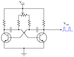
A student desires to use this circuit as the basis for a pulse-width modulation (PWM) power controller, to vary the amount of power delivered to a DC load. Since the oscillator circuit is built to produce weak signals and not deliver power directly to a load, the student adds a power MOSFET to switch heavy load currents:
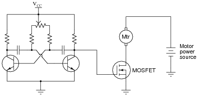
Correlate the duty cycle of the oscillator’s output signal with motor power. In other words, describe how increases and decreases in signal duty cycle affect the amount of power delivered to the electric motor.
Reveal answerThe greater the duty cycle, the more power delivered to the motor.
Follow-up question: how do you recommend a suitable oscillator frequency be determined for this motor control circuit? Describe how you might experiment with the circuit to determine a suitable frequency without performing any calculations.
Notes:As review, ask your students to identify what type of MOSFET this is (type of channel, and either depletion or enhancement mode), and what the proper oscillator signal amplitude should be to drive the MOSFET alternately between cutoff and saturation.