Facebook
 Google
 GitHub
 Linkedin
Discrete Semiconductor Devices and Circuits
Signal Modulation
31 questions By Tony R. Kuphaldt
-
Question 19 of 31
Explain why it is important for the final power transistor(s) in a PWM power control circuit to operate at full cutoff and full saturation, and not in the linear (active) mode in between those two extremes. What might happen if the power transistor(s) were to be less than cut-off or less than saturated when carrying load current?
Reveal answerTransistor power dissipation will increase if operating in its “linear” range of operation rather than being completely cut off or saturated. This decreases its service life as well as the energy efficiency of the circuit.
Notes:Review with your students what it means for a transistor to be in “cutoff” or in “saturation,” if they are not familiar with these terms or if it has been a while since they have studied this. A clear understanding of this concept is crucial to their being able to understand the efficiency of PWM power control.
-
Question 20 of 31
If a pulse-width modulated (PWM) signal is sent to a passive integrator circuit from a circuit capable of both sourcing and sinking current (as is the case with the dual-MOSFET output stage), the output will be a DC voltage (with some ripple):
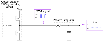
Determine the relationship between the PWM signal’s duty cycle and the DC voltage output by the integrator. What does this suggest about PWM as a means of communicating information, such as analog data from a measuring device?
Reveal answerThere is a direct-proportional relationship between duty cycle and DC output voltage in this circuit, making it possible for a PWM signal to represent analog data.
Follow-up question #1: why is it important that the circuit generating the PWM signal for the integrator be able to both source and sink current?
Follow-up question #2: what would have to be done to reduce the ripple voltage at the integrator’s output?
Notes:Although it should not be difficult for students to discern the relationship between duty cycle and DC output voltage, the application of this relationship to data communication might be difficult for some students to grasp, especially on their own. Further elaboration on your part may be necessary.
An excellent example of this principle applied is the generation of an analog voltage by a 1-bit digital circuit. This technique is useful in microcontroller systems where output ports may be scarce, provided that ripple voltage (or slow response) is not a problem.
-
Question 21 of 31
Plot what the frequency spectrum would look like for a pure (undistorted) 1 MHz sine wave:

Reveal answer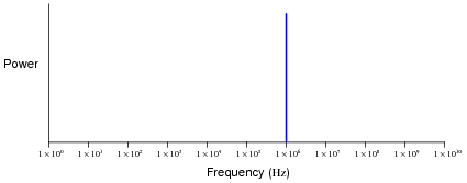
Notes:This question probes students’ knowledge of frequency spectra and logarithmic scales. Note that with a pure sine wave, there is but a single peak on the frequency spectrum.