
 Facebook
 Google
 GitHub
 Linkedin
DC Electric Circuits
Voltage Divider Circuits
37 questions By Tony R. Kuphaldt
-
Question 28 of 37
One of the resistors in this voltage divider circuit has failed (either open or shorted). Based on the voltage readings shown at each load, comparing what each load voltage is versus what it should be, determine which resistor has failed and what type of failure it is:
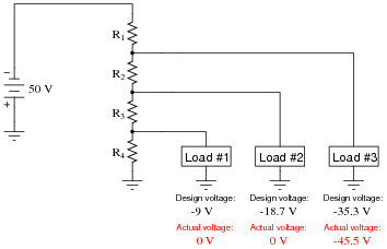
Reveal answerResistor R2 has failed open.
Notes:Use this question as an opportunity to discuss troubleshooting strategies with your students. A helpful hint in dealing with this kind of problem is to categorize each load voltage as either being greater or less than normal. Forget the negative signs here: we’re dealing strictly with absolute values (in other words, -25 volts is a “greater” voltage than -20 volts). Once each load voltage has been categorized thusly, it is possible to isolate the location and nature of the fault without having to deal with numbers at all!
-
Question 29 of 37
One of the resistors in this voltage divider circuit has failed (either open or shorted). Based on the voltage readings shown at each load, comparing what each load voltage is versus what it should be, determine which resistor has failed and what type of failure it is:
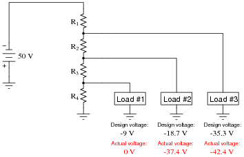
Reveal answerResistor R3 has failed open.
Notes:Use this question as an opportunity to discuss troubleshooting strategies with your students. A helpful hint in dealing with this kind of problem is to categorize each load voltage as either being greater or less than normal. Forget the negative signs here: we’re dealing strictly with absolute values (in other words, -25 volts is a “greater” voltage than -20 volts). Once each load voltage has been categorized thusly, it is possible to isolate the location and nature of the fault without having to deal with numbers at all!
-
Question 30 of 37
Size the resistor in this voltage divider circuit to provide 3.2 volts to the load, assuming that the load will draw 10 mA of current at this voltage:

As part of your design, include the power dissipation ratings of both resistors.
Reveal answerR = 1 kΩ. The 470 Ω resistor will fare well even with a (low) power dissipation rating of 1/8 watt, though the 1 kΩ resistor will need to be rated in excess of 1/4 watt.
Notes:Ask your students what would change in this divider circuit if the load were to suddenly draw more, or less, current.





Plus signs are missing from these questions and answers, such as in question 11, where the denominator of the voltage divider equation appears as “R1 R2 R3” instead of “R1+R2+R3”. Same in the answer to question 15. Likely elsewhere as well, as Find shows no results for “+” anywhere on the page. I’m using Chrome 88.0.4324.182 on Windows 10, but same on Firefox & Edge. HTML source for the page shows it as “R1 R2 R3”, so it isn’t just a display problem.
Iam a student and i need an explain for this answers how can I get an explanation ?
Ca any one tell in detail how
The formula got formed like this !! ( ER= Et(R/Rt)) thank you