
 Facebook
 Google
 GitHub
 Linkedin
DC Electric Circuits
Voltage Divider Circuits
37 questions By Tony R. Kuphaldt
-
Question 13 of 37
Calculate both the maximum and the minimum amount of voltage obtainable from this potentiometer circuit (as measured between the wiper and ground):
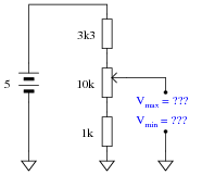
Reveal answerVmax = 3.85 volts
Vmin = 0.35 volts
Notes:Be sure to ask your students how they obtained their answers, not just what the answers are. There is more than one correct way to analyze this circuit!
Incidentally, there is nothing significant about the use of European schematic symbols in this question. I did this simply to provide students with more exposure to this schematic convention.
-
Question 14 of 37
Calculate both the maximum and the minimum amount of voltage that each of the voltmeters will register, at each of the potentiometer’s extreme positions:
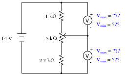
Reveal answerFor upper voltmeter:
Vmax = 10.24 volts Vmin = 1.71 volts
For lower voltmeter:
Vmax = 12.29 volts Vmin = 3.76 volts
Follow-up question: identify the positions in which the potentiometer wiper must be set in order to obtain all four of the voltage readings shown above.
Notes:Be sure to ask your students how they obtained their answers, not just what the answers are. There is more than one correct way to analyze this circuit!
-
Question 15 of 37
As adjustable devices, potentiometers may be set at a number of different positions. It is often helpful to express the position of a potentiometer’s wiper as a fraction of full travel: a number between 0 and 1, inclusive. Here are several pictorial examples of this, with the variable m designating this travel value (the choice of which alphabetical character to use for this variable is arbitrary):

Using an algebraic variable to represent potentiometer position allows us to write equations describing the outputs of voltage divider circuits employing potentiometers. Note the following examples:
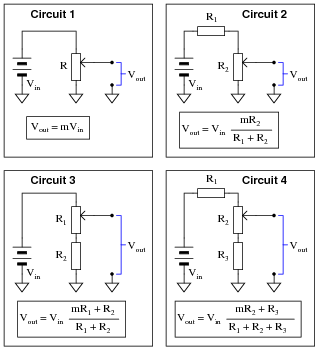
Algebraically manipulate these four equations so as to solve for m in each case. This will yield equations telling you where to set each potentiometer to obtain a desired output voltage given the input voltage and all resistance values (m = …).
Reveal answerCircuit 1: m = Vout VinCircuit 2: m = Vout(R1 + R2) Vin R2Circuit 3: m = Vout(R1 + R2) − VinR2 Vin R1Circuit 4: m = Vout(R1 + R2 + R3) − VinR3 Vin R2Hint: in order to avoid confusion with all the subscripted R variables (R1, R2, and R3) in your work, you may wish to substitute simpler variables such as a for R1, b for R2, etc. Similarly, you may wish to substitute x for Vin and y for Vout. Using shorter variable names makes the equations easier to manipulate. See how this simplifies the equation for circuit 2:
Circuit 2 (original equation): y = x ( mb a + b) Circuit 2 (manipulated equation): m = y(a + b) bxNotes:The main purpose of this question is to provide algebraic manipulation practice for students, as well as shown them a practical application for algebraic substitution. The circuits are almost incidental to the math.






Plus signs are missing from these questions and answers, such as in question 11, where the denominator of the voltage divider equation appears as “R1 R2 R3” instead of “R1+R2+R3”. Same in the answer to question 15. Likely elsewhere as well, as Find shows no results for “+” anywhere on the page. I’m using Chrome 88.0.4324.182 on Windows 10, but same on Firefox & Edge. HTML source for the page shows it as “R1 R2 R3”, so it isn’t just a display problem.
Iam a student and i need an explain for this answers how can I get an explanation ?
Ca any one tell in detail how
The formula got formed like this !! ( ER= Et(R/Rt)) thank you