
 Facebook
 Google
 GitHub
 Linkedin
DC Electric Circuits
Voltage Divider Circuits
37 questions By Tony R. Kuphaldt
-
Question 10 of 37
Draw an equivalent schematic diagram for this circuit, then calculate the voltage dropped by each of these resistors, given a battery voltage of 9 volts. The resistor color codes are as follows (assume 0% error on all resistor values):
- R1 = Brn, Grn, Red, Gld
- R2 = Yel, Vio, Org, Gld
- R3 = Red, Grn, Red, Gld
- R4 = Wht, Blk, Red, Gld
- R5 = Brn, Blk, Org, Gld
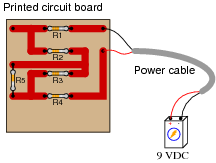
Compare the voltage dropped across R1, R2, R3, and R4, with and without R5 in the circuit. What general conclusions may be drawn from these voltage figures?
Reveal answer
With R5 in the circuit: Without R5 in the circuit: ER1 = 0.226 volts ER1 = 0.225 volts ER2 = 7.109 volts ER2 = 7.05 volts ER3 = 0.303 volts ER3 = 0.375 volts ER4 = 1.36 volts ER4 = 1.35 volts Notes:Ask your students to describe the “with R5 / without R5” voltage values in terms of either increase or decrease. A general pattern should be immediately evident when this is done.
-
Question 11 of 37
The formula for calculating voltage across a resistor in a series circuit is as follows:
VR = Vtotal ( R Rtotal) In a simple-series circuit with one voltage source and three resistors, we may re-write this formula to be more specific:
VR1 = Vsource ( R1 R1 + R2 + R3) Suppose we have such a series circuit with a source voltage of 15 volts, and resistor values of R1 = 1 kΩ and R2 = 8.1 kΩ. Algebraically manipulate this formula to solve for R3 in terms of all the other variables, then determine the necessary resistance value of R3 to obtain a 0.2 volt drop across resistor R1.
Reveal answerR3 = Vsource ( R1 VR1) − (R1 + R2) R3 = 65.9 kΩ
Notes:This question provides students with another practical application of algebraic manipulation. Ask individual students to show their steps in manipulating the voltage divider formula to solve for R3, so that all may see and learn.
-
Question 12 of 37
What will happen to the voltages across resistors R1 and R2 when the load is connected to the divider circuit?

Reveal answerWhen the load is connected across R2, R2’s voltage will “sag” (decrease) while R1’s voltage will rise (increase).
Notes:This is a very important concept to be learned about voltage divider circuits: how they respond to applications of load. Not a single calculation need be done to arrive at the answer for this question, so encourage your students to think qualitatively rather than quantitatively. Too many students have the habit of reaching for their calculators when faced with a problem like this, when they really just need to apply more thought.






Plus signs are missing from these questions and answers, such as in question 11, where the denominator of the voltage divider equation appears as “R1 R2 R3” instead of “R1+R2+R3”. Same in the answer to question 15. Likely elsewhere as well, as Find shows no results for “+” anywhere on the page. I’m using Chrome 88.0.4324.182 on Windows 10, but same on Firefox & Edge. HTML source for the page shows it as “R1 R2 R3”, so it isn’t just a display problem.
Iam a student and i need an explain for this answers how can I get an explanation ?
Ca any one tell in detail how
The formula got formed like this !! ( ER= Et(R/Rt)) thank you