
 Facebook
 Google
 GitHub
 Linkedin
AC Electric Circuits
Autotransformers
12 questions By Tony R. Kuphaldt
-
Question 10 of 12
Devices called step regulators are sometimes used in electrical power distribution systems to boost or suppress line voltages, typically to a maximum of 10%:

The “Line” side of this autotransformer is the source of power, and the “Load” side connects to those devices consuming electrical power. The “Reversing switch” alters the transformer’s function from boost to buck.
Determine which switch position is “boost” and which is “buck,” and then determine which way the moving contact (the arrow symbol) needs to be moved in order to increase the voltage output, and to decrease the voltage output.
Reveal answerWhen the reversing switch is in the left position, the regulator output voltage is reduced. When the switch is in the right position, the regulator output voltage is increased. Moving the contact further to the right increases the amount of boost or buck, depending on which position the reversing switch is in.
Incidentally, the zig-zag pattern of the windings is not standard for electronic schematic diagrams, though it is more common in electrical power system diagrams. I’ll let you research how they draw resistors in these types of diagrams!
Notes:The solution to this question may be easier for some to recognize if the regulator circuit is re-drawn using normal electronic schematic diagrams. Another tip is to simplify the schematic diagram by removing all the different tap positions, and draw the circuit using the full series winding.
It is important for students to realize that there are different types of electrical schematic diagrams. Power diagram symbolism is often confusing to people familiar with electronic schematic symbolism, and visa-versa.
-
Question 11 of 12
Calculate all currents in this autotransformer circuit, assuming perfect (100%) efficiency:
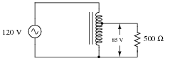
Reveal answer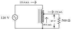
Follow-up question: based on these current figures, what economic advantage does an autotransformer have over a conventional transformer in terms of manufacturing cost?
Notes:Discuss with your students the pro’s and con’s of autotransformers over regular transformers. Of course, there is the obvious disadvantage: loss of isolation between primary and secondary circuits. If this is not a problem, though, there are substantial advantages to be realized in using an autotransformer over a conventional transformer.
-
Question 12 of 12
Suppose the load in this circuit suddenly stops receiving power:

Your first step in troubleshooting is to take some voltage measurements:
- VAB = 120 V
- VEC = 0 V
- VDC = 120 V
Based on these measurements, where do you think the fault is in this circuit, and what type of fault is it?
Reveal answerI’ll let you determine the most likely failure on your own!
Notes:Ask your students to think of some other possibilities for failure in this circuit besides their first hypothesis. Also, discuss how you would verify (double-check) all hypotheses, with different meter measurements.


