Facebook
 Google
 GitHub
 Linkedin
Discrete Semiconductor Devices and Circuits
Bipolar Junction Transistors as Switches
34 questions By Tony R. Kuphaldt
-
Question 10 of 34
In each of the following circuits, the light bulb will energize when the pushbutton switch is actuated. Assume that the supply voltage in each case is somewhere between 5 and 30 volts DC (with lamps and resistors appropriately sized):

However, not all of these circuits are properly designed. Some of them will function perfectly, but others will function only once or twice before their transistors fail. Identify the faulty circuits, and explain why they are flawed.
Reveal answerCircuits 3, 5, and 6 are flawed, because the emitter-base junctions of their transistors are overpowered every time the switch closes.
Hint: draw the respective paths of switch and lamp current for each circuit!
Notes:This is a very important concept for students to learn if they are to do any switch circuit design - a task not limited to engineers. Technicians often must piece together simple transistor switching circuits to accomplish specific tasks on the job, so it is important for them to be able to design switching circuits that will be reliable. A common mistake is to design a circuit so that the transistor receives full supply voltage across the emitter-base junction when ön,” as three of the circuits in this question do. The result is sure destruction of the transistor if the supply voltage is substantial.
Circuit #3 is a tricky one! The presence of a resistor might fool some students into thinking base current is limited (as is the case with circuit #2).
-
Question 11 of 34
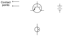
Draw the necessary wire connections so that bridging the two contact points with your finger (creating a high-resistance connection between those points) will turn the light bulb on:
Reveal answer
Notes:Once students learn to identify the two current paths (base versus collector), especially the proper directions of current for each, the interconnections become much easier to determine.
Some students may place the light bulb on the emitter terminal of the transistor, in a common-collector configuration. This is not recommended, since it places the light bulb in series with the controlling (base) current path, and this will have the effect of impeding base current, and therefore the controlled (light bulb) current. Given the very high electrical resistance of human skin, this circuit needs all the gain we can possibly muster!
This circuit works well if an LED is substituted for the incandescent lamp.
-
Question 12 of 34
The ignition system of a gasoline-powered internal combustion automobile engine is an example of a transformer operated on DC by means of an oscillating switch contact, commonly referred to as the contact “points”:
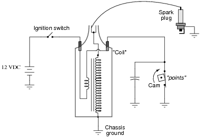
The cam-actuated “point” contacts open every time a spark is needed to ignite the air-fuel mixture in one of the engine’s cylinders. Naturally, these contacts suffer a substantial amount of wear over time due to the amount of current they must make and break, and the frequency of their cycling.
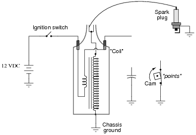
This device was seen by automotive engineers as a prime candidate for replacement with solid-state technology (i.e., a transistor). If a transistor could take the place of mechanical “point” contacts for making and breaking the ignition coil’s current, it should result in increased service life.
Insert a transistor into the following circuit in such a way that it controls the ignition coil’s current, with the “point” contacts merely controlling the transistor’s state (turning it on and off):
Reveal answer
Follow-up question: assuming the primary winding of the “coil” has an inductance of 9 mH an a wire resistance of 0.4 Ω, determine the amount of time necessary to build to full current once the transistor or points have turned on (after 5 time constants’ worth of time).
Notes:Ask your students, “what is the purpose of the capacitor in this circuit?” Inform them that without it, the points would have “burned up” very quickly, and that the transistor will fail almost immediately!
Some of your students familiar with engine ignition systems will notice that there is no distributor for multiple spark plugs. In other words, this circuit is for a single-cylinder engine! I chose not to draw a distributor in this schematic just to keep things simple.