Facebook
 Google
 GitHub
 Linkedin
Discrete Semiconductor Devices and Circuits
Bipolar Junction Transistors as Switches
34 questions By Tony R. Kuphaldt
-
Question 16 of 34
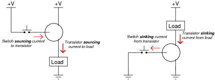
Choose the right type of bipolar junction transistor for each of these switching applications, drawing the correct transistor symbol inside each circle:
Reveal answer
Follow-up question: explain why neither of the following transistor circuits will work. When the pushbutton switch is actuated, the load remains de-energized:

Notes:Discuss with your students the meaning of the words “sourcing” and “sinking” in case they are not yet familiar with them. These are very common terms used in electronics (especially digital and power circuitry!), and they make the most sense in the context of conventional flow current notation.
In order for students to properly choose and place each transistor to make the circuits functional, they must understand how BJTs are triggered on (forward-biasing of the base-emitter junction) and also which directions the currents move through BJTs. The two example circuits shown in this question are very realistic.
-
Question 17 of 34
Choose the right type of bipolar junction transistor for each of these switching applications, drawing the correct transistor symbol inside each circle:
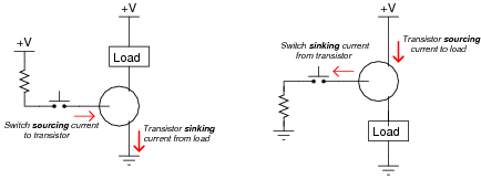
Also, explain why resistors are necessary in both these circuits for the transistors to function without being damaged.
Reveal answer
Follow-up question: explain why neither of the following transistor circuits will work. When the pushbutton switch is actuated, the load remains de-energized:

Notes:Discuss with your students the meaning of the words “sourcing” and “sinking” in case they are not yet familiar with them. These are very common terms used in electronics (especially digital and power circuitry!), and they make the most sense in the context of conventional flow current notation.
In order for students to properly choose and place each transistor to make the circuits functional, they must understand how BJTs are triggered on (forward-biasing of the base-emitter junction) and also which directions the currents move through BJTs. The two example circuits shown in this question are very realistic.
-
Question 18 of 34
In this circuit, the electric motor is supposed to turn on whenever the cadmium sulfide photocell is darkened:

Unfortunately, though, the motor refuses to turn on no matter how little light strikes the photocell. In an attempt to troubleshoot the circuit, a technician measures voltage between the collector and emitter terminals of the transistor with the photocell covered by a piece of dark tape, and measures full battery voltage. The technician also measures voltage between the collector and base terminals of the transistor, and measures full battery voltage. At that point, the technician gives up and hands the problem to you.
Based on this information, what do you suspect is faulty in this circuit, and how might you determine the exact location of the fault? Also, identify what you know to be not faulted in the circuit, based on the information given here.
Reveal answerThe battery, and its connections to the rest of the circuit, are in good condition. Also, we know that the motor is not failed open. In all likelihood, the transistor is not being “told” to turn on.
Notes:It is just as important for your students to be able to identify what is not faulted in a system as it is for them to be able to identify what is faulted. Replacing components that are not faulted is expensive and wasteful!
An essential part of answering this question is what the photocell does when light strikes it. Obviously, it undergoes a change in electrical resistance, but which way? This is something your students will have to determine before they can successfully troubleshoot the system. If they do not understand what the system is supposed to do, they will be helpless in interpreting what it is presently doing.