Facebook
 Google
 GitHub
 Linkedin
Discrete Semiconductor Devices and Circuits
Bipolar Junction Transistors as Switches
34 questions By Tony R. Kuphaldt
-
Question 13 of 34
Electronic ignition systems for gasoline-powered engines typically use a device called a reluctor to trigger the transistor to turn on and off. Shown here is a simple reluctor-based electronic ignition system:
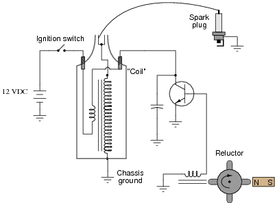
Explain how this circuit functions. Why do you think the triggering device is called a “reluctor”? What advantage(s) does this circuit have over a mechanical “point” operated ignition system?
Reveal answerThe “reluctor” generates pulses of current to the transistor’s base to turn it on and off. The word “reluctor” is applied to this device in honor of a certain magnetic principle you should know!
Notes:Discuss the advantages of a reluctor-triggered ignition system with your students. As far as I am aware, the system possesses no disadvantages when compared against mechanical point-driven systems.
An interesting side note: one method of testing a reluctor-driven ignition system at high frequencies was to hold the tip of a soldering gun (not a soldering iron!) next to the pickup coil and pull the trigger. The strong magnetic field produced by the gun’s high current (60 Hz AC) would trigger the ignition system to deliver 60 sparks per second.
Some of your students familiar with engine ignition systems will notice that there is no distributor for multiple spark plugs. In other words, this circuit is for a single-cylinder engine! I chose not to draw a distributor in this schematic just to keep things simple.
-
Question 14 of 34
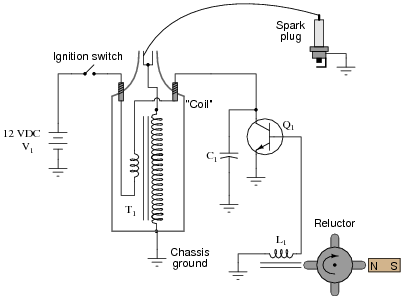
Predict how all component voltages and currents in this circuit will be affected as a result of the following faults. Consider each fault independently (i.e. one at a time, no multiple faults):
- Transistor Q1 fails open (collector-to-emitter):
- Transistor Q1 fails shorted (collector-to-emitter):
- Reluctor magnet weakens:
- Capacitor C1 fails shorted:
- Capacitor C1 fails open:
- Transformer (“coil”) T1 primary winding fails open:
- Transformer (“coil”) T1 secondary winding fails open:
For each of these conditions, explain why the resulting effects will occur.
Reveal answer- Transistor Q1 fails open (collector-to-emitter): No current through T1 primary or secondary, no high-voltage pulses across T1 secondary, full 12 volts (constant) across C1, voltage pulses still seen across L1, no spark at spark plug.
- Transistor Q1 fails shorted (collector-to-emitter): Constant current through T1 primary, no high-voltage pulses across T1 secondary, nearly 0 volts across C1, very weak voltage pulses across L1, no spark at spark plug.
- Reluctor magnet weakens: Smaller voltage pulses across L1, smaller current pulses through T1 primary, smaller voltage pulses across T2 secondary, weak or no spark at spark plug.
- Capacitor C1 fails shorted: Constant current through T1 primary, no high-voltage pulses across T1 secondary, nearly 0 volts across C1, normal voltage pulses across L1, no spark at spark plug.
- Capacitor C1 fails open: Excessive voltage pulses seen at Q1 collector (with respect to ground), very rapid failure of Q1.
- Transformer (“coil”) T1 primary winding fails open: No current through T1 primary or secondary, no high-voltage pulses across T1 secondary, zero volts (constant) across C1, voltage pulses still seen across L1, no spark at spark plug.
- Transformer (“coil”) T1 secondary winding fails open: All voltages and currents fairly normal except for no voltage across T1 secondary and no spark at spark plug, perhaps slightly greater voltage pulses seen at Q1 collector with respect to ground.
Notes:The purpose of this question is to approach the domain of circuit troubleshooting from a perspective of knowing what the fault is, rather than only knowing what the symptoms are. Although this is not necessarily a realistic perspective, it helps students build the foundational knowledge necessary to diagnose a faulted circuit from empirical data. Questions such as this should be followed (eventually) by other questions asking students to identify likely faults based on measurements.
-
Question 15 of 34
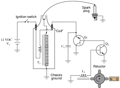
Predict how all component voltages and currents in this circuit will be affected as a result of the following faults. Consider each fault independently (i.e. one at a time, no multiple faults):
- Transistor Q2 fails open (collector-to-emitter):
- Transistor Q1 fails shorted (collector-to-emitter):
- Capacitor C1 fails shorted:
- Capacitor C1 fails open:
- Reluctor coil L1 fails open:
For each of these conditions, explain why the resulting effects will occur.
Reveal answer- Transistor Q2 fails open (collector-to-emitter): No current through T1 primary or secondary, no high-voltage pulses across T1 secondary, full 12 volts (constant) across C1, no current through any terminal of Q1, voltage pulses still seen across L1, no spark at spark plug.
- Transistor Q1 fails shorted (collector-to-emitter): Constant current through T1 primary, no high-voltage pulses across T1 secondary, nearly 0 volts across C1, voltage pulses still seen across L1, no spark at spark plug.
- Capacitor C1 fails shorted: Constant current through T1 primary, no high-voltage pulses across T1 secondary, nearly 0 volts across C1, normal voltage pulses across L1, no spark at spark plug.
- Capacitor C1 fails open: Excessive voltage pulses seen at Q1 collector (with respect to ground), very rapid failure of Q1 and possibly Q2.
- Reluctor coil L1 fails open: No current through T1 primary or secondary, no high-voltage pulses across T1 secondary, full 12 volts (constant) across C1, full 12 volts (constant) across Q2 collector-to-emitter, no voltage pulses seen across L1, no spark at spark plug.
Notes:The purpose of this question is to approach the domain of circuit troubleshooting from a perspective of knowing what the fault is, rather than only knowing what the symptoms are. Although this is not necessarily a realistic perspective, it helps students build the foundational knowledge necessary to diagnose a faulted circuit from empirical data. Questions such as this should be followed (eventually) by other questions asking students to identify likely faults based on measurements.