Facebook
 Google
 GitHub
 Linkedin
Discrete Semiconductor Devices and Circuits
Bipolar Junction Transistors as Switches
34 questions By Tony R. Kuphaldt
-
Question 28 of 34
Explain the operation of this “H-bridge” motor control circuit:

At any given moment, how many transistors are turned on and how many are turned off? Also, explain what would happen to the function of the circuit if resistor R1 failed open.
Reveal answerTwo transistors are on at any given time, and the other two are off. If R1 fails open, the motor will not be able to go in the “forward” (Fwd) direction.
Challenge question: what type of DC motor is this drive circuit designed for? Shunt-wound, series-wound, compound, or permanent magnet? Explain your answer.
Notes:The “H-drive” circuit is a very common method of reversing polarity to a DC motor (or other polarity-sensitive load), using only a single-pole switch. Very, very large electric motor “drives” have been based on this same design.
-
Question 29 of 34
Predict how the motor function in this circuit will be affected as a result of the following faults. Consider each fault independently (i.e. one at a time, no multiple faults):

- Transistor Q1 fails open (collector-to-emitter):
- Transistor Q2 fails open (collector-to-emitter):
- Transistor Q3 fails open (collector-to-emitter):
- Transistor Q4 fails open (collector-to-emitter):
- Resistor R1 fails open:
- Resistor R2 fails open:
- Resistor R3 fails open:
- Transistor Q3 fails shorted (collector-to-emitter):
- Transistor Q4 fails shorted (collector-to-emitter):
For each of these conditions, explain why the resulting effects will occur.
Reveal answer- Transistor Q1 fails open (collector-to-emitter): Motor fails to turn in “reverse” direction, can still turn in “forward” direction.
- Transistor Q2 fails open (collector-to-emitter): Motor fails to turn in “forward” direction, can still turn in “reverse” direction.
- Transistor Q3 fails open (collector-to-emitter): Motor fails to turn in “forward” direction, can still turn in “reverse” direction.
- Transistor Q4 fails open (collector-to-emitter): Motor fails to turn in “reverse” direction, can still turn in “forward” direction.
- Resistor R1 fails open: Motor fails to turn in “forward” direction, can still turn in “reverse” direction.
- Resistor R2 fails open: Motor fails to turn in “reverse” direction, can still turn in “forward” direction.
- Resistor R3 fails open: Motor cannot turn in either direction.
- Transistor Q3 fails shorted (collector-to-emitter): Motor turns in “forward” direction even when the switch is in the center (off) position.
- Transistor Q4 fails shorted (collector-to-emitter): Motor turns in “reverse” direction even when the switch is in the center (off) position.
Notes:The purpose of this question is to approach the domain of circuit troubleshooting from a perspective of knowing what the fault is, rather than only knowing what the symptoms are. Although this is not necessarily a realistic perspective, it helps students build the foundational knowledge necessary to diagnose a faulted circuit from empirical data. Questions such as this should be followed (eventually) by other questions asking students to identify likely faults based on measurements.
-
Question 30 of 34
The circuit shown here is part of a digital logic gate circuit:
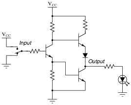
Logic circuits operate with their transistors either fully “on” or fully “off,” never in-between. Determine what state the LED will be in (either on or off) for both switch positions. You may find it helpful to trace currents and label all voltage drops in this circuit for the two switch states:
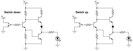
For your voltage drop calculations, assume the following parameters:
- VCC = 5 volts
- VBE (conducting) = 0.7 volts
- VCE (conducting) = 0.3 volts
- Vf (regular diode conducting) = 0.7 volts
- Vf (LED conducting) = 1.6 volts
Reveal answerSwitch down, LED on; switch up, LED off.
Notes:The circuit shown in this question is a partial TTL inverter gate. I opted to simplify the circuit (omitting the “steering” diodes usually found at the input) for the sake of simplicity, so students could concentrate their attention on the two transistor stages following. Although this circuit may appear intimidating, it is not that difficult to trace currents and calculate voltage drops if one approaches it methodically.