Facebook
 Google
 GitHub
 Linkedin
Discrete Semiconductor Devices and Circuits
Bipolar Junction Transistors as Switches
34 questions By Tony R. Kuphaldt
-
Question 25 of 34
Calculate all labeled currents in this Darlington pair circuit (shown in this schematic in conventional flow notation), assuming a typical forward base-emitter junction voltage drop of 0.7 volts for each transistor:
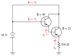
Reveal answer- I1 = 465.8 mA
- I2 = 197.0 μA
- I3 = 17.92 mA
- I4 = 466.0 mA
Notes:Have your students come to the front of the class, either as individuals or as groups, and present problem-solving techniques for determining the unknown currents.
-
Question 26 of 34
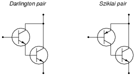
An alternative to the Darlington pair is the Sziklai pair, formed by a complementary pair of bipolar transistors:
Complete the following circuits, showing how a switch would be connected to each of the transistor pairs to exert control over the electric motor:
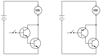
Reveal answer
Follow-up question: why would anyone want to use either a Darlington or Sziklai pair when a single transistor is able to switch current on its own? What advantage do either of these transistor pair configurations give over a single transistor?
Notes:Sziklai pair circuits are often not discussed in electronics texts until the subject of audio power amplifiers, where the Sziklai pair is offered as an alternative to complementary power transistors in a push-pull circuit (where the final output transistors are both NPN instead of one being NPN and the other PNP). There is nothing wrong, however, with introducing the Sziklai pair configuration in the context of a simple switching circuit as it is done here.
-
Question 27 of 34
Explain how the one toggle switch is able to switch both transistors on and off simultaneously in this motor control circuit:
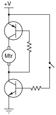
Reveal answerThe switch exerts direct control over the lower transistor, which then indirectly turns on the upper transistor. When both transistors are turned on, the motor runs.
Notes:This question is really a precursor to analyzing the H-bridge motor drive circuit.