Facebook
 Google
 GitHub
 Linkedin
Discrete Semiconductor Devices and Circuits
Bipolar Junction Transistors as Switches
34 questions By Tony R. Kuphaldt
-
Question 31 of 34
One of the simplest transistor “logic” circuits used in computer circuitry is the so-called inverter gate. Its logic diagram symbol is this:

Inverters are often bundled six to a “DIP” (Dual-Inline Package) module, where all gates share the same two power supply connections (“Vcc” and “Ground”), like this:
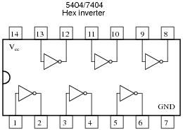
When constructed with bipolar junction transistors, the internal schematic diagram of a single inverter gate looks something like this:

Being a digital logic circuit, it only “understands” two states: on and off. As you can see, a SPDT switch provides signal input into the logic gate, either full supply voltage (VCC) or no voltage at all (Gnd).
Determine the voltage across the load resistance for each of these switch states. Based on your analysis, what is the logical function of an “inverter” gate?
Reveal answerAn “inverter” gate simply reverses the logic state of the input.
Notes:There is much to analyze in this circuit, and this question is not intended to be a full introduction to digital logic. It does, however, provide a preview of things to come, as well as an excellent opportunity to analyze diode and transistor circuitry in the simplest possible way: either fully “on” or fully “off”.
One tactic I have found useful as an instructor for analyzing complex circuits in front of a class is to project the image onto a whiteboard using a bright computer projector. Then, you may use dry-erase markers on the whiteboard to “comment” the diagram with voltage and current notations as you proceed to analyze the circuit with your students. Analyzing the circuit for a different logic state is easy: merely erase the “comments” made previously, and the schematic itself is unchanged, ready to be “marked up” again.
-
Question 32 of 34
There is a problem somewhere in this electronic ignition circuit. The “coil” does not output high voltage as it should when the reluctor spins. A mechanic already changed the coil and replaced it with a new one, but this did not fix the problem.
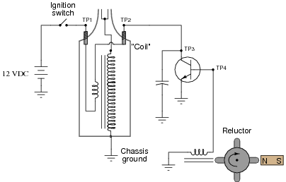
You are then asked to look at the circuit to see if you can figure out what is wrong. Using your multimeter, you measure voltage between TP1 and ground (12 volts DC) and also between TP2 and ground (12 volts DC). These voltage readings do not change at all as the reluctor spins.
From this information, identify two possible faults that could account for the problem and all measured values in this circuit, and also identify two circuit elements that could not possibly be to blame (i.e. two things that you know must be functioning properly, no matter what else may be faulted). The circuit elements you identify as either possibly faulted or properly functioning can be wires, traces, and connections as well as components. Be as specific as you can in your answers, identifying both the circuit element and the type of fault.
- Circuit elements that are possibly faulted
- 1.
- 2.
- Circuit elements that must be functioning properly
- 1.
- 2.
Reveal answerNote: the following answers are not exhaustive. There may be more circuit elements possibly at fault and more circuit elements known to be functioning properly!
- Circuit elements that are possibly faulted
- Transistor failed open between collector and emitter
- Reluctor coil has failed open
- Circuit elements that must be functioning properly
- Battery
- Ignition switch
Notes:Ask your students to identify means by which they could confirm suspected circuit elements, by measuring something other than what has already been measured.
Troubleshooting scenarios are always good for stimulating class discussion. Be sure to spend plenty of time in class with your students developing efficient and logical diagnostic procedures, as this will assist them greatly in their careers.
-
Question 33 of 34
There is a problem somewhere in this electronic ignition circuit. The “coil” does not output high voltage as it should when the reluctor spins. A mechanic already changed the coil and replaced it with a new one, but this did not fix the problem.
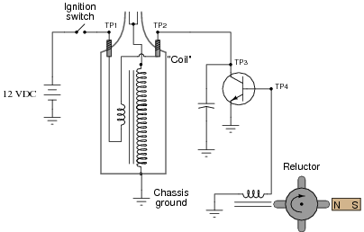
You are then asked to look at the circuit to see if you can figure out what is wrong. Using your multimeter, you measure voltage between TP1 and ground (12 volts DC) and also between TP2 and ground (0 volts DC). These voltage readings do not change at all as the reluctor spins.
From this information, identify two possible faults that could account for the problem and all measured values in this circuit, and also identify two circuit elements that could not possibly be to blame (i.e. two things that you know must be functioning properly, no matter what else may be faulted). The circuit elements you identify as either possibly faulted or properly functioning can be wires, traces, and connections as well as components. Be as specific as you can in your answers, identifying both the circuit element and the type of fault.
- Circuit elements that are possibly faulted
- 1.
- 2.
- Circuit elements that must be functioning properly
- 1.
- 2.
Reveal answerNote: the following answers are not exhaustive. There may be more circuit elements possibly at fault and more circuit elements known to be functioning properly!
- Circuit elements that are possibly faulted
- Transistor failed shorted between collector and emitter
- Capacitor failed shorted
- Circuit elements that must be functioning properly
- Battery
- Ignition switch
Notes:Ask your students to identify means by which they could confirm suspected circuit elements, by measuring something other than what has already been measured.
Troubleshooting scenarios are always good for stimulating class discussion. Be sure to spend plenty of time in class with your students developing efficient and logical diagnostic procedures, as this will assist them greatly in their careers.