Facebook
 Google
 GitHub
 Linkedin
Discrete Semiconductor Devices and Circuits
Bipolar Junction Transistors as Switches
34 questions By Tony R. Kuphaldt
-
Question 4 of 34
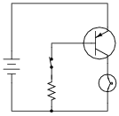
Calculate all component voltage drops in this circuit, assuming a supply voltage of 15 volts, an emitter-base forward voltage drop of 0.7 volts, and a (saturated) emitter-collector voltage drop of 0.3 volts:
Reveal answer
Notes:An interesting point that some students may bring up is the 0.4 volt drop across the base-collector junction. Attentive students will note that this junction is supposed to be reverse-biased, but Kirchhoff’s Voltage Law clearly specifies the polarity of that 0.4 volt drop, and it is in the direction one would expect for forward biasing of that junction. An examination of the energy diagram for a conducting bipolar junction transistor is really necessary to explain why that junction is considered to be reverse-biased.
-
Question 5 of 34
A student attempts to build a circuit that will turn a DC motor on and off with a very delicate (low current rating) pushbutton switch. Unfortunately, there is something wrong with the circuit, because the motor does not turn on no matter what is done with the switch:
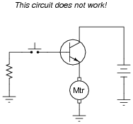
Correct the error(s) in this circuit, showing how it must be set up so that the transistor functions as intended.
Reveal answer
Notes:It is very important for your students to learn how the base current controls the collector current in a BJT, and how to use this knowledge to properly set up switching circuits. This is not difficult to learn, but it takes time and practice for many students to master. Be sure to spend adequate time discussing this concept (and circuit design techniques) so they all understand.
-
Question 6 of 34
A stepper motor is a special type of electric motor typically used for digital positioning systems. The motor shaft rotates by alternately energizing its coils in a specific sequence. These electromagnet coils draw a fair amount of DC current (several amperes is not uncommon for heavy-duty stepper motors), and as such are usually triggered by power transistors:

The control circuit that usually sends pulse signals to the base of the power transistors is not shown in this diagram, for simplicity. Your task is to draw a pushbutton switch in this schematic diagram showing how the first motor coil could be manually energized and de-energized. Be sure to note the directions of currents through the transistor, so that your switch is installed correctly!
Also, explain the purpose of the diode connected in parallel with the motor coil. Actually, there will be one of these diodes for each of the motor coils, but the other three are not shown for the sake of simplicity.
Reveal answer
The diode prevents damage to the transistor resulting from inductive “kickback” each time the motor coil is de-energized.
Notes:It is very important for your students to learn how the base current controls the collector current in a BJT, and how to use this knowledge to properly set up switching circuits. This is not difficult to learn, but it takes time and practice for many students to master. Be sure to spend adequate time discussing this concept (and circuit design techniques) so they all understand.