Facebook
 Google
 GitHub
 Linkedin
Discrete Semiconductor Devices and Circuits
Differential Transistor Amplifiers
19 questions By Tony R. Kuphaldt
-
Question 13 of 19
This circuit is part of a weather monitoring station. Wind speed is measured by the voltage output from a permanent-magnet DC generator, turned by a set of vanes. A light bulb lights up when the wind speed passes a threshold (“trip”) value, established by the potentiometer:
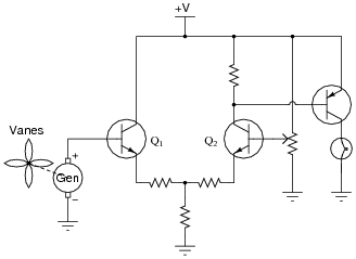
Based on your understanding of differential pair circuits, is this a high-speed wind indicating circuit or a low-speed wind indicating circuit?
Reveal answerThe light bulb energizes when the wind speed decreases below the threshold value.
Notes:Ask your students to explain their reasoning in obtaining their answers. What happens in this circuit as the generator voltage increases, and as it decreases? Which way do we adjust the potentiometer to increase the trip point? How do we know this?
Let your students know that this circuit is a simple example of what is called a comparator: a circuit that compares two voltages against each other and generates an output corresponding to which voltage is greater.
-
Question 14 of 19
What is common-mode voltage, and how should a differential amplifier (ideally) respond to it?
Reveal answer“Common-mode voltage” is the amount of voltage common to both inputs of a differential amplifier. Ideally, a differential amplifier should reject this common-mode voltage, only amplifying the difference between the two input voltages.
Follow-up question: what does the phrase common-mode rejection ratio (CMRR) mean for a differential amplifier?
Notes:Ask your students to provide examples of common-mode voltage to a differential amplifier. For example, x amount of voltage on one input and y amount of voltage on the other constitutes z amount of common-mode voltage . . .
-
Question 15 of 19
If we connect the two transistor bases together in a differential pair circuit, it can only see common-mode input voltage (no differential input voltage):
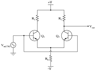
An important performance parameter of any differential amplifier is its common-mode voltage gain. Ideally, a differential-input amplifier should ignore any and all common-mode voltage, but in reality there is always some amplification of common-mode voltage. We need to figure out how much of that there will be in any differential-pair circuit.
To help us analyze this circuit (with both inputs tied together so it only sees common-mode input voltage), I will re-draw it in such a way that reflects the symmetrical nature of the circuit:
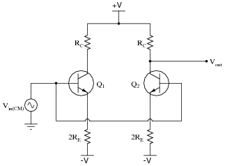
First, explain why this re-drawing is justified, and then write the equation describing the common-mode voltage gain of this circuit, in terms of the component values.
Reveal answerIf the transistors are identical, and receive the same input signal at their base terminals, they will pass the same amount of current from collector to emitter. This means the “tail” resistor’s current (IRE) is evenly split between the two transistors. With an even split of current, the one resistor will act the same as two resistors of twice that value, each one carrying only the current of one transistor.
Re-drawn like this, it should be plain to see that the differential pair acts as a swamped common-emitter amplifier, with the common-mode voltage gain described by the following equation:
$$A_{V(CM)} = \frac{R_C}{r'_e+2R_E}$$
Follow-up question: what component value(s) should be altered to minimize common-mode voltage gain in a differential pair circuit, and why?
Notes:The purpose of this question is to have students recognize what factors in a differential pair circuit influence common-mode voltage gain, and then to realize that the value of the tail resistor has great influence over common-mode gain, while at the same time having negligible influence over differential gain.