Facebook
 Google
 GitHub
 Linkedin
Digital Circuits
Latch Circuits
26 questions By Tony R. Kuphaldt
-
Question 4 of 26
Some digital circuits are considered to have active-low inputs, while others have active-high inputs. Explain what each of these terms means, and how we might identify which type of input(s) a digital circuit has.
Reveal answerAn “active-low” input is one where that particular gate function is activated or invoked on a low logic state. Active-low inputs are identified by inversion bubbles (or inversion wedges) drawn at the IC input terminals. For example, the Enable input (EN) for the following integrated circuit is active-low, meaning the chip is enabled when that input line is held at ground potential:

This S-R latch circuit has active-low preset ([PRE]) and clear ([CLR]) inputs, meaning the latch circuit will be preset and cleared when each of these inputs are grounded, respectively:

Active-high inputs, conversely, engage their respective functions when brought to power supply rail (VDD or VCC) potential. As one might expect, an active-high input will not have an inversion bubble or wedge next to the input terminal.
Challenge question: to the surprise of many students, there are a great number of digital logic circuit types built with active-low inputs. Explain why. Hint: most of these circuit types and functions were pioneered with TTL logic rather than CMOS logic.
Notes:Active-low inputs tend to confuse many students, hence my unusually long and descriptive answer.
-
Question 5 of 26
The circuit shown here is called an S-R latch:
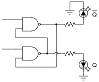
Identify which of the two input lines is the Set, and which is the Reset, and then write a truth table describing the function of this circuit.
Reveal answer
Follow-up question: why are the inputs referred to as [Set] and [Reset], rather than just Set and Reset?
Notes:The “latch” state is the most interesting in this circuit. Discuss what this means with your students, especially since it is impossible to describe the “latch” state in terms of fixed 1’s and 0’s. Also ask your students to identify the “invalid” state of this latch circuit, and to explain why it is called “invalid”.
Discuss the active-low nature of this latch circuit’s inputs. Explain to your students that many digital functions have active-low inputs, and that it is common to denote those inputs by writing a Boolean complementation bar over the input’s name.
-
Question 6 of 26
Latch circuits are often drawn as complete units in their own block symbols, rather than as a collection of individual gates:
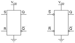
This simplifies schematic drawings where latches are used, much as the use of gate symbolism (as opposed to drawing individual transistors and resistors) simplifies the diagrams of more elementary digital circuits.
From the block symbols shown in this question, is there any way to determine which of the S-R latches is built with NOR gates, and which one is built with NAND gates?
Reveal answerThis is a bit of a trick question. If NOR and NAND are the only gate choices available, then the left latch is made from NOR gates and the right latch is made from NAND gates. However, it is possible to make S-R latches out of gates other than NOR or NAND.
Challenge question: can you think of other gate types that could be used to build S-R latch circuits? Hint: there are at least two alternatives to NOR and NAND!
Notes:If students become stuck on the challenge question, just whisper “DeMorgan’s Theorem” to them and watch what happens!