Facebook
 Google
 GitHub
 Linkedin
Digital Circuits
Latch Circuits
26 questions By Tony R. Kuphaldt
-
Question 13 of 26
Here, a gated S-R latch is being used to control the electric power to a powerful ultraviolet lamp, used for sterilization of instruments in a laboratory environment:
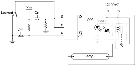
Based on your knowledge of how gated S-R latches function, what is the purpose of the “Lockout” switch? Also, explain how the CMOS latch is able to exert control over the high-power lamp (i.e. explain the operation of the interposing devices between the latch and the lamp).
Now, suppose the lab personnel want to add a feature to the ultraviolet sterilization chamber: an electric solenoid door lock, so that personnel can open the door to the chamber only if the following conditions are met:
- Lamp is off
- “Lockout” switch is sending a “low” signal to the latch’s Enable input
Modify this circuit so that it energizes the door lock solenoid, allowing access to the chamber, only if the above conditions are both true.
Reveal answerThe “Lockout” switch effectively disables the “On” and “Off” controls when it sends a “low” signal to the latch’s Enable input.
This circuit uses both a solid-state relay (SSR) and an electromechanical relay for interposing between the latch and the lamp. These devices allow the low-power latch circuit to exert control over the high-power lamp.
Here is one possibility for the door lock control:
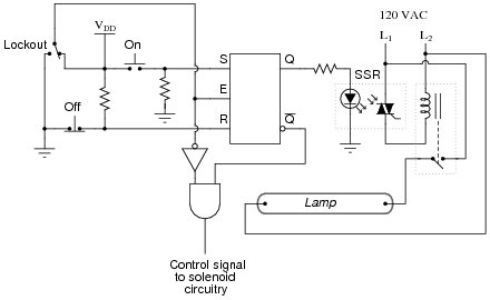
Follow-up question: there are better (safer) ways to accomplish this same function. For instance, suppose the TRIAC inside the SSR were to fail shorted, maintaining power to the lamp even when the latch goes into the “reset” mode. Would the door-lock logic shown here prevent someone from opening the door and getting exposed to the strong ultraviolet light? Explain your answer!
Challenge question: why not just use one interposing device: either an SSR, or an electromagnetic relay? Why both types of devices in the same circuit?
Notes:The purpose of the “Lockout” switch is fairly simple, and should be easy for the students to explain. On the other hand, the design and implementation of a door lock safety circuit is a more complex question, deserving of discussion because it involves several important and realistic considerations:
- How do we go from a simple verbal description of logical conditions (lamp off, enable low) to an actual gate circuit?
- What is the safest strategy to use in determining when it is safe to open the door?
- How should the door lock logic interpose to the solenoid itself (this is not shown in the answer!)?
- How would the principles of lock-out/tag-out apply to this system, if we were approaching the problem from the perspective of maintenance personnel rather than lab (operations) personnel?
The challenge question gets students thinking in terms of real-life currents and voltages, and the limitations of each device.
-
Question 14 of 26
A variation on the gated S-R latch circuit is something called the D-latch:
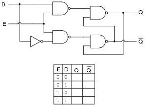
Complete the truth table for this D latch circuit, and identify which rows in the truth table represent the set, reset, and latch states, respectively.
Reveal answer
Notes:Since this gate does not actually have “Set” and “Reset” inputs, ask your students to explain what conditions define the “set” and “reset” states. Note that these state labels may be applied to any type of latch circuit.
To many of your students, this latch circuit may seem rather useless. Explain to them that this basic latch may be used to form memory cells, with each D latch storing 1 binary bit of information! Ask your students to explain, in their own words, how the latching action of this circuit constitutes a memory function. Under what condition(s) will the stored information in a D latch memory cell be lost?
-
Question 15 of 26
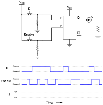
Complete the timing diagram, showing the state of the Q output over time as the input switches are actuated. Assume that Q begins in the low state on power-up:
Reveal answer
Follow-up question: complete a schematic diagram showing how this latch circuit could turn a motor on and off through a MOSFET.

Also, comment on whether your MOSFET sources current to the motor or sinks current from the motor.
Notes:Some students may be confused about the width of the last pulse on the Q output. Remind them that Q follows D for as long as the Enable input is activated!