Facebook
 Google
 GitHub
 Linkedin
Digital Circuits
Latch Circuits
26 questions By Tony R. Kuphaldt
-
Question 19 of 26
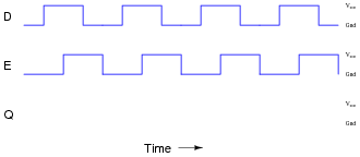
In many types of digital systems, a set of square-wave signals are phase-shifted from each other by 90o. Such a phase relationship is called quadrature.
Determine the output of a D-type latch for this pair of quadrature signals, applied to the D and E inputs over time:
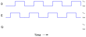
Then, determine the output of a D-type latch when the phase relationship is reversed, (D leading E by 90o, instead of E leading D by 90o):
Reveal answer

Notes:Students need to be proficient in analyzing pulse diagrams, especially with latch circuits (and later, with flip-flops), because these types of circuits often find application in pulse-driven systems.
-
Question 20 of 26
This one-way street is equipped with an alarm to signal drivers going the wrong way. The sensors work by light beams being broken when an automobile passes between them. The distance between the sensors is less than the length of a normal car, which means as a car passes by, first one beam is broken, then both beams become broken, then only the last beam is broken, then neither beam is broken. The sensors are phototransistors sensitive only to the narrow spectrum of light emitted by the laser light sources, so that ambient sunlight will not “fool” them:
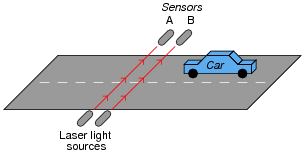
Both sensors connect to inputs on a D-type latch, which is then connected to some other circuitry to sound an alarm when a car goes down the road the wrong way:

The first question is this: which way is the correct way to drive down this street? From left to right, or from right to left (as shown in the illustration)?
The second question is, how will the system respond if sensor A’s laser light source fails? What will happen if sensor B’s laser light source fails?
Reveal answerLeft-to-right is the correct driving direction for this street.
If sensor A’s light source fails, the alarm will never activate. A failed light source for sensor B will have different effects on the system, depending on whether sensor A was sending a “high” or a “low” signal to the latch circuit at the time B’s light source failed. I’ll let you figure out which way triggers the alarm!
Notes:This question is a great problem-solving exercise. Students must figure out how to set it up so that they may apply the rules of latch circuits and gate circuits, then they must analyze it correctly! Devote plenty of classroom time to a discussion of this problem.
Students may show a reluctance to draw a timing diagram when they approach this problem, even when they realize the utility of such a diagram. Instead, many will try to figure the circuit out just by looking at it. Note the emphasis on the word “try.” This circuit is much more difficult to figure out without a timing diagram! Withhold your explanation of this circuit until each student shows you a timing diagram for it. Emphasize the fact that this step, although it consumes a bit of time, is actually a time-saver in the end.
It is easy as an instructor to focus so intently on teaching electronic theory that other practical matters become neglected. Electronic technicians and engineers do not simply work on circuits; they work on systems that happen to employ electronic circuits. Ultimately, nearly every electronic circuit they work with will have some relationship to the physical world. Problem solving exercises in school must include scenarios similar to real life, where conditions and functions other than electronics have a role in determining the solution. Only by exposing students to problems requiring them to think beyond pure electronics will they become adequately prepared to meet the challenges of their future careers.
-
Question 21 of 26
Identify at least one component fault that would cause the “[Q]” LED to always remain off, no matter what was done with the input switches.

For each of your proposed faults, explain why it will cause the described problem.
Reveal answer- Resistor R3 failed open.
- NOR gate U1 output failed low.
- Resistor R1 failed open (provided enough ambient electrical noise to activate a floating gate input).
- “Set” switch contacts failed shorted.
Notes:Latch circuits can be confusing due to their use of positive feedback. Questions such as this are important tools for helping develop your students’ understanding of latch circuits.