
 Facebook
 Google
 GitHub
 Linkedin
DC Electric Circuits
Series-Parallel DC Circuits
41 questions By Tony R. Kuphaldt
-
Question 34 of 41
A student built this resistor circuit on a solderless breadboard, but made a mistake positioning resistor R3. It should be located one hole to the left instead of where it is right now:
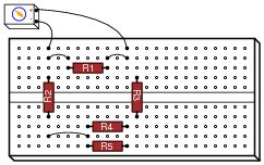
Determine what the voltage drop will be across each resistor, in this faulty configuration, assuming that the battery outputs 9 volts.
- • R1 = 2 k Ω VR1 =
- • R2 = 1 k Ω VR2 =
- • R3 = 3.3 k Ω VR3 =
- • R4 = 4.7 k Ω VR4 =
- • R5 = 4.7 k Ω VR5 =
Reveal answerRather than tell you each voltage drop, I’ll give you this one hint: there is only one resistor in this breadboard circuit that has voltage across it! All the other resistors in this circuit are de-energized, thanks to the misplacement of resistor R3.
Notes:Tell your students that the fault shown in this question is quite typical. The hole spacings on solderless breadboards are small enough that it is surprisingly easy to mis-locate a component in the manner shown.
Point out to your students (if they haven’t already noticed) that no calculations are necessary to answer this question! It may be answered through simple, qualitative analysis alone.
-
Question 35 of 41
Suppose you were designing a circuit that required two LEDs for “power on” indication. The power supply voltage is 15 volts, and each LED is rated at 1.6 volts and 20 mA. Calculate the dropping resistor sizes and power ratings:

After doing this, a co-worker looks at your circuit and suggests a modification. Why not use a single dropping resistor for both LEDs, economizing the number of components necessary?

Re-calculate the dropping resistor ratings (resistance and power) for the new design.
Reveal answerWith two resistors: R1 = R2 = 670 Ω, rated for at least 0.268 watts (1/2 watt would be a practical rating).
With one resistor: R1 = 335 Ω, rated for at least 0.536 watts (1 watt would be a practical rating).
Follow-up question: if there were no perfectly sized resistors sized to choose from (which there most likely will not be!), would it be safer to choose a higher-value resistor or a lower-value resistor for these applications? For example, if you needed 670 Ω but the closest options on hand were 680 Ω and 500 Ω, which resistance value would you select? Explain your answer.
Notes:If students are not yet familiar with the “ V” symbol used to denote the positive power supply connection in this schematic, let them know that this is a very common practice in electronic notation, just as it is common to use the ground symbol as a power supply connection symbol.
The follow-up question is a very practical one, for it is seldom that you have the exact components on-hand to match the requirements of a circuit you are building. It is important to understand which way is safer to err (too large or too small) when doing “as-built” design work.
-
Question 36 of 41
Calculate all voltages and currents in this circuit:
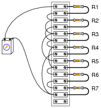
The battery voltage is 15 volts, and the resistor values are as follows:
- R1 = 1 kΩ
- R2 = 3.3 kΩ
- R3 = 4.7 kΩ
- R4 = 2.5 kΩ
- R5 = 10 kΩ
- R6 = 1.5 kΩ
- R7 = 500 Ω
Reveal answerR1 = 1 kΩ ER1 = 4.016 V IR1 = 4.016 mA R2 = 3.3 kΩ ER2 = 6.522 V IR2 = 1.976 mA R3 = 4.7 kΩ ER3 = 6.522 V IR3 = 1.388 mA R4 = 2.5 kΩ ER4 = 4.462 V IR4 = 1.785 mA R5 = 10 kΩ ER5 = 6.522 V IR5 = 652 μA R6 = 1.5 kΩ ER6 = 3.347 V IR6 = 2.231 mA R7 = 500 Ω ER7 = 1.116 V IR7 = 2.231 mA Notes:Your students will benefit greatly from having a clean schematic diagram to work off of. However, do not supply this for them! Let them figure out how to derive a schematic diagram from the illustrated circuit.
Students often have difficulty formulating a method of solution: determining what steps to take to get from the given conditions to a final answer. While it is helpful at first for you (the instructor) to show them, it is bad for you to show them too often, lest they stop thinking for themselves and merely follow your lead. A teaching technique I have found very helpful is to have students come up to the board (alone or in teams) in front of class to write their problem-solving strategies for all the others to see. They don’t have to actually do the math, but rather outline the steps they would take, in the order they would take them.
By having students outline their problem-solving strategies, everyone gets an opportunity to see multiple methods of solution, and you (the instructor) get to see how (and if!) your students are thinking. An especially good point to emphasize in these “open thinking” activities is how to check your work to see if any mistakes were made.






How did you guys find the answer for Q5, figure 6